Licensed as KC2OQG (September 20, 2005 - December 3, 2007)
Licensed as N2AWA (December 4, 2007 - present)
ITU Region 2 (Zone 8) / CQ Zone 5 / Grid FN12gx
New York State / Ontario County
QTH Elevation 182 meters (597 feet)
| N2AWA (vanity call) Expires December 4, 2027 | FCC License Renewal | Eligible to renew October 5, 2027 (60 days prior to expiration) |
| N2AWA (vanity call) Expires December 4, 2017 | FCC License Renewal | Eligible to renew October 5, 2017 (60 days prior to expiration) |
History of Amateur Radio Station N2AWAI remember hearing about amateur ("HAM") radio when I was a kid back in the late 1960s and early 1970s. It certainly had an element of intrigue, and I was casually acquainted with one or two amateur operators ("HAMs") over the years, but never allocated the time to learn more about it, and develop my own interests, until around 2005.
My personal exploration of amateur radio began in September 2005 when I visited the Rochester Amateur Radio Association (RARA) website. I began studying the American Radio Relay League (ARRL) Element 2 (Technician Class) manual on Sunday September 4, and was prepared to take the exam September 17, which was the date of the next local Volunteer Examiner Coordinator (VEC) testing session. Unfortunately, I was out of town that day (at the Antique Radio Swap Meet in Kutztown, Pennsylvania). So I searched for other VEC sessions via the ARRL website and conveniently made arrangements (thanks to AK3M) to take the exam with the Lehigh Valley Amateur Radio Club (LVARC) in Allentown, Pennsylvania at 7:30 p.m. Friday night, September 16, 2005. I passed the exam, which was held at the Lehigh Valley Red Cross building, and the F.C.C. issued me the call sign KC2OQG on September 20, 2005. It was great to finally be an amateur radio operator after procrastinating for so many years!
After I got the Technician Class license, a generous former co-worker and local HAM Tim (WB2PAY) loaned me his Kenwood TH-22AT (2 meter VHF - 144 MHz - 148 MHz) hand-held ("HT" a.k.a. "Handie-Talkie") portable transceiver so that I might get a better sense of what was happening, and take part in the conversations on the 2 meter band (144-148 MHz) until I got my own rig. He also loaned me a 2 meter J-Pole antenna (custom made from aluminum tubing) and a nice large tripod, along with 20' of RG-58 coaxial cable. Armed with this modest arsenal, I was able to reach most of the local FM repeaters. When I returned the Kenwood TH-22AT hand-held radio (November 4, 2005), he then loaned me a 1982 Kenwood TS-530S HF transceiver (1.8 MHz - 29.7 MHz) (160 meters - 10 meters) so that I was able to listen to "live" CW (Morse Code) before I took the exam to get my General Class license. We also set up, and tuned a ½ wave 20 meter dipole antenna inside my shack. After I got my General Class ticket (see below), I made quite a few phone (voice) contacts to the southern United States (Florida, Georgia, Texas, North Carolina, West Virginia) using the 20 meter ½ wave dipole and running "barefoot" (no external amplifier) with the Kenwood TS-530S.
On September 19, 2005 I joined Rochester Amateur Radio Association (RARA) and enrolled in their 12-week course on General Class license theory (ARRL Element 3). At the same time, I began studying Morse Code by listening to the ARRL "Your Introduction to Morse Code" cassette tapes. I listened to the tapes in my car every weekday for two months during my 70 minute round-trip commute! I also practiced the code at home with a borrowed copy (thanks to KC2KQT) of the CD-ROM version of the ARRL course, and by using a code synthesizer, which a local HAM (W2SKY) loaned me for the duration. In addition to these methods, I also downloaded Morse Academy on my computer and practiced it that way. I wanted to be absolutely sure I was prepared for that five-word-per-minute ARRL Element 1 exam!
I took both the General Class (ARRL Element 3) and the five-word-per-minute Morse code exams (ARRL Element 1) on Saturday, November 19, 2005 at 10:30 a.m. at Rochester Institute of Technology (RIT). So I got my General Class ticket the week of Thanksgiving. Incidentally, I was prepared to take both the ARRL Element 1 and Element 3 exams on Sunday, October 16, but missed the monthly RARA testing session by one day, so I had to wait for the November session to roll around. The extra month of studying worked to my advantage, because I got a perfect score on both exams. Note that fifteen months later, in a historic move, (February 23, 2007) the F.C.C. eliminated Morse Code as a requirement for any/all amateur radio licenses.
I began studying the ARRL "Element 4" (Extra Class) theory on November 26, 2005 and took the exam on Saturday, February 18, 2006 at 10:30 a.m. at RIT during the monthly RARA VEC testing session. The F.C.C. issued my Extra Class license on February 23, 2006 and I received the hard copy of the license in the mail on March 1, 2006. I never knew the exact score on that test, but it was a satisfying moment, to be sure.
As of this writing, I have made numerous 2 meter (VHF) and 70 cm (UHF) phone contacts as well as quite a few HF phone contacts on various bands. However, I have not made a lot of CW (Morse Code) contacts. CW requires a lot of focus, dedication and practice. I enjoy the VHF and UHF FM bands because there are usually a lot of HAMs to interact with in my region, but I recognize that the challenge of HF DX (working distant stations, in both phone and CW mode) is what keeps many amateurs hooked on the hobby for many years. Since getting the Extra Class ticket, I have spent some time increasing my CW proficiency and experimenting with various antenna configurations.
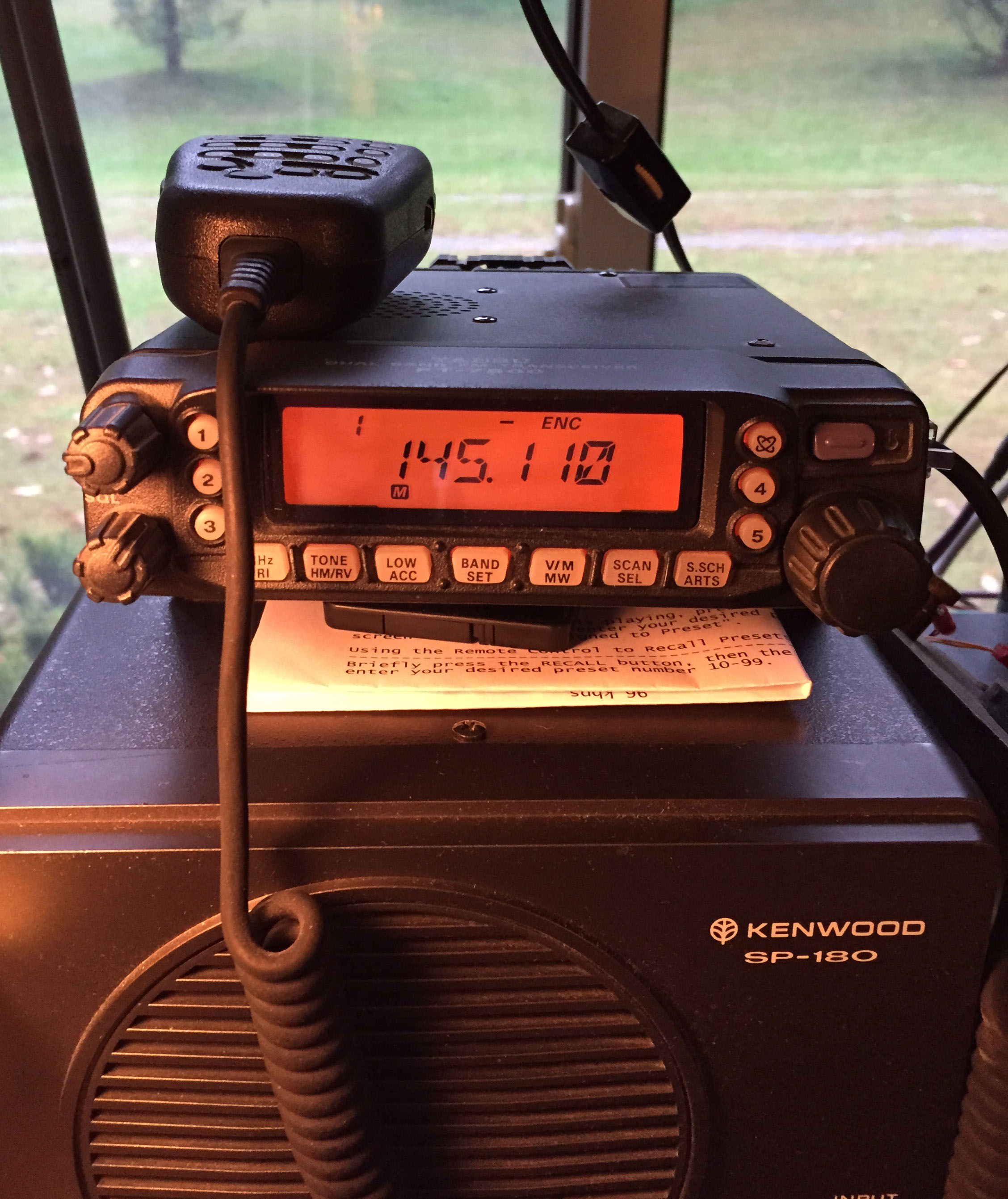
From 2006 through 2012: Shared Net Control Station (NCS) duties on Sunday nights for the "Monroe County FM Net" (K2RRA / 146.88 MHz), which existed as a forum to buy, sell and trade HAM radio equipment and distribute information pertinent to the local HAM community. The Net was terminated at the end of 2012. Also hosted an occasional "Newbie Net" on the same 2-meter FM repeater until that Net finally ran its course.
Vanity Call - N2AWAOn November 16, 2007, I applied to the F.C.C. for the vanity call sign N2AWA and it was granted on December 4, 2007. This is a nice call for several reasons. First, the CW weight is much "lighter" than KC2OQG, which had a CW weight of 86 (a lot of tapping on the straight key). N2AWA has a CW weight of 54, so it is quicker to send via Morse Code. Secondly, "2" is my home QTH state (New York) and third, the "AWA" suffix was meaningful because of my membership in the Antique Wireless Association (AWA).
More Radio Trivia (non-Amateur)On June 12, 1981, the F.C.C. issued my "Restricted Radiotelephone Operator Permit" (for broadcast radio) to fulfill the legal requirements of hosting a weekly, three-hour classical music program (Bach, Mozart, Beethoven, etc.) at WRUR (88.5 FM / University of Rochester). It was a Saturday show (11:00 a.m. – 2:00 p.m.), which began on May 16, and ran for 11 weeks, through August 1, 1981.
I became a Short Wave Listener (SWL) in May of 1989 when I got a Grundig "Satellit International 400" radio. I used the World Radio and Television Handbook (WRTH) to identify the AM/FM/SW stations heard from around the country and the globe. At that time, some of the international broadcast stations would send QSL cards and/or printed copies of their broadcast schedules upon request. I recall getting Christmas cards and schedules from Radio Havana (Cuba) for several years after sending them a signal report.
>From 1990 to 1995: Honed my on-air etherizer skills hosting a weekly, three-hour Sunday night jazz music program at WITR (89.7 FM / Rochester Institute of Technology).
On April 5, 2009, began a weekly gig as a production engineer (a.k.a. knob twister) at WYSL (1040 kHz AM and 92.1 MHz FM [via translator W221CL]) in Avon, New York. Sold air time, wrote and produced client advertisements, recorded daily weather forecasts, and engineered five "live" Sunday morning programs (three church services, and two talk shows) from 5:30 a.m. until noon.
I am also interested in European AM/FM/SW radios (circa 1955-1972). My favorite brands are Grundig, Telefunken, and Blaupunkt, but there are many European "exotics" to choose from. I enjoy maintaining and restoring vacuum tube radios, and have a workbench and reference library (both ever-evolving) dedicated to the hobby.
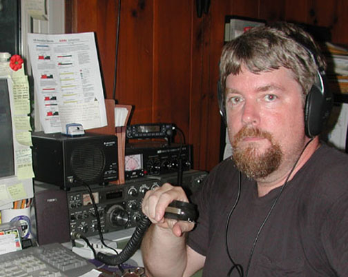
Amateur Radio Station - KC2OQG / August 21, 2006
The earliest (and only) known photo of me operating as a ham (original call sign KC2OQG) with the Kenwood "TS-530S" transceiver, MFJ "949E" tuner, and Yaesu "FT-7800R" FM transceiver. This was 15 months before I got the vanity call sign N2AWA, and also 15 months before I added the AM equipment (Johnson "Viking Valiant" transmitter, and Hallicrafters "S-40" receiver) to the shack.
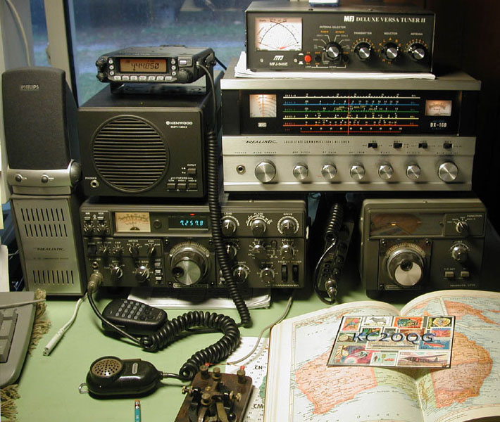
Amateur Radio Station - KC2OQG / November 18, 2006
Still licensed as KC2OQG, this shows the addition of a Realistic "DX-160 Solid State Communications Receiver" with original, model "SP 150 Communications Speaker" (far left, bottom). The DX-160 was purchased 18-may-2006 ($66 + $20 freight) on eBay. The hand-held microphone for the Kenwood TS-5330S (see enlarged photo) was original to the rig.
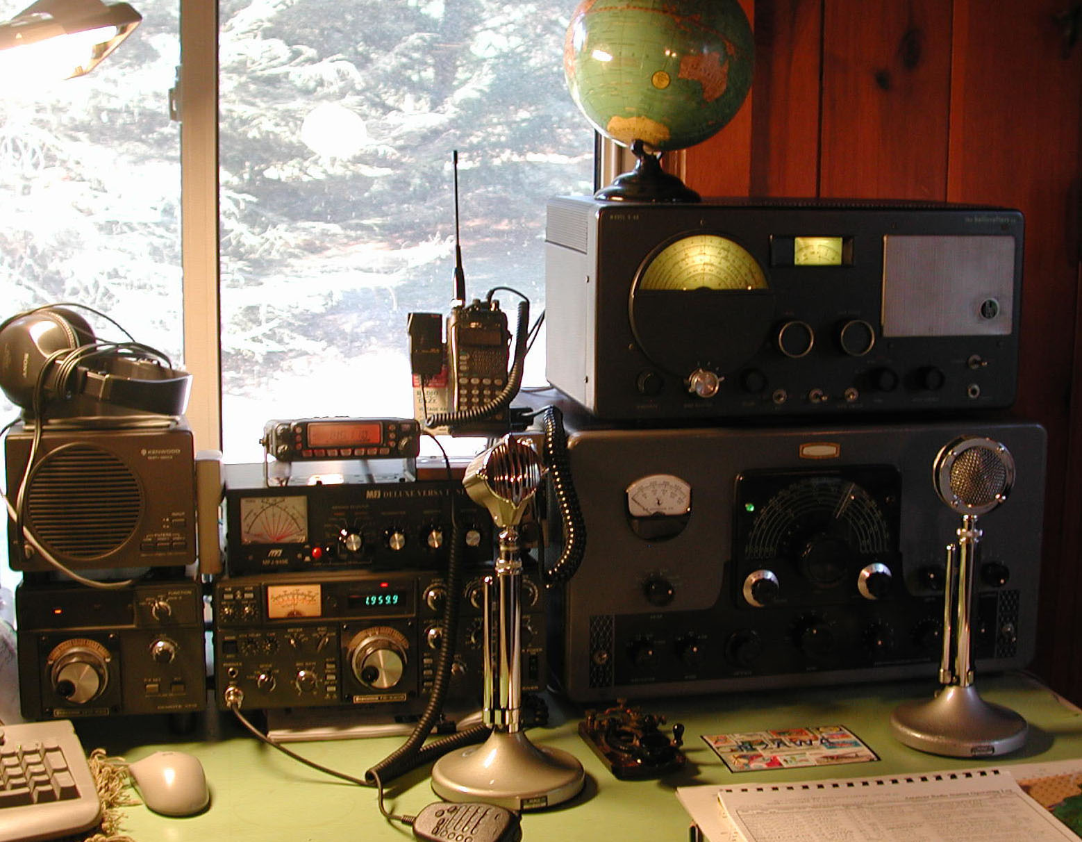
Amateur Radio Station - N2AWA / January 20, 2008
On February 25, 2006 I became the third owner of the 1982 Kenwood HF transceiver shown in the photo. The Kenwood components of the set include a TS-530S (100W HF transceiver), SP-180 (remote speaker), VFO-240 (remote VFO for split channel operation), and the hand-held microphone (not shown). I had the TS-530S "on loan" (without the VFO-240 and SP-180) in my shack – courtesy Tim (WB2PAY) from November 4, 2005 through February 25, 2006, at which time it became a permanent fixture in the shack. I paid $300 for the Kenwood station including the VFO-240 and SP-180 and the hand-held mic.
The right side of the photograph features a 1955-1962 E.F. Johnson Viking Valiant AM/CW transmitter and a 1946 Hallicrafters S-40 receiver (sitting on top of the Valiant). The Hallicrafters S-40 receiver came to the shack on September 29, 2007 ($125 at the Elmira Hamfest) and the Viking Valiant transmitter arrived on November 2, 2007 ($325 at the annual RARA auction). Both the S-40 and Valiant were refurbished by yours truly. They were put on the air together as a set for the first time on the eve of Thursday, January 10, 2008. My first AM contact was with Ray Jr. (KC2OHL).
Also note the circa 1948 Astatic (Conneaut, Ohio) D-104 microphone with a T-UG8 stand
(amplified, but bypassed)and non-amplified "grip to talk" UG8 stand, and a DN-HZ (a.k.a. "bullet" or "cucumber") head. The original style D-104 microphone (with "lolly pop" head) came to the shack January 4, 2008 ($20.00). It had a two-conductor, shielded cable with an Amphenol Type 80-MC2M two-pin connector for use with the Viking Valiant. It was missing the base-plate cover, so I finally found another D-104 (August 2009) that had the base-plate cover (non-amplified base). I think I paid $30 for the "new" D-104 and sold the original one at the Elmira Hamfest on September 26, 2009 for $15.
Also (in the photo, sitting atop the Kenwood TS-530S) is an MFJ Deluxe Versa Tuner II (MFJ-949E) 300W antenna tuner. More detail on the MFJ tuner can be found elsewhere on this page.
Finally, there is a Yaesu FT-7800R dual band (2m / 70cm) FM "mobile" transceiver on top of the MFJ 949-E tuner, and an ICOM IC-W32A dual band hand-held "HT" FM transceiver to the right of that. Wedged vertically between the MFJ Versa Tuner and the Viking Valiant (behind the stalk of the Astatic DN-HZ bullet head) is a Uniden "PRO 520XL" 40 channel C.B. radio (11 meter – "Children's Band") that I purchased new in 1988. The C.B. radio has not seen much use lately, but it works fine, and (incredibly) is still in production as of this writing (July 2013) – 25 years after I purchased it.
The "WARC" Bands
The World Administrative Radio Conference met in Geneva, Switzerland in 1979. Among the many topics covered at this meeting was the creation of three new amateur radio bands: 30 meters, 17 meters and 12 meters. Today, these three bands are referred to collectively as the WARC bands by amateur radio operators.
Kenwood "TS-530S" OverviewThe Kenwood TS-530S follows in the tradition of the successful TS-520S. It is designed for SSB and CW modes in the 160 through 10 meter HAM bands, and additionally includes the 30, 17 and 12 meter WARC bands. Input power is 220W PEP SSB and 180W DC CW.
Kenwood TS-530S Transceiver |
||||
|
Tube |
Schematic Ref. Nr. |
Type |
Reference |
Price |
|
12BY7A |
V1 (RF unit) |
driver |
x |
|
|
6146B |
V1 (final unit) |
final amplifier |
x |
|
|
6146B |
V2 (final unit) |
final amplifier |
www.r-type.org/exhib/aaa0546.htm |
x |
The Kenwood TS-530S is a hybrid radio because most of the circuitry is solid-state but the RF stage includes a Type 12BY7A driver tube and the final has a pair of Type 6146B amplifier tubes. This transceiver does not have general coverage receive. Requires 120 VAC 50/60 Hz. Dimensions and weight: 13.3 x 5.3 x 13.37 inches 28.2 lbs. (333 x 133 x 333 mm 12.8 kg).
Kenwood TS-530S Features
- 160-10 meters
- WARC Bands (30, 17, 12 meters)
- VOX
- NB (noise blanker). The "Noise Blanker" circuit screens out certain types of impulse noise. Sometimes useful in automobile-mounted radios, most NBs do little against the bulk of SW interference.
- 25 kHz Marker
- RIT/XIT
- Speech Processor
- IF Shift
- RF Attenuator
- 120 VAC Operation
- Kenwood remote VFO (VFO 240) for split frequency operation.
- Kenwood remote speaker (SP-180)
- Manual: bama.edebris.com/manuals/kenwood/ts530s
- Tune-up procedure (courtesy K4EAA): www.k4eaa.com/tune-up.htm
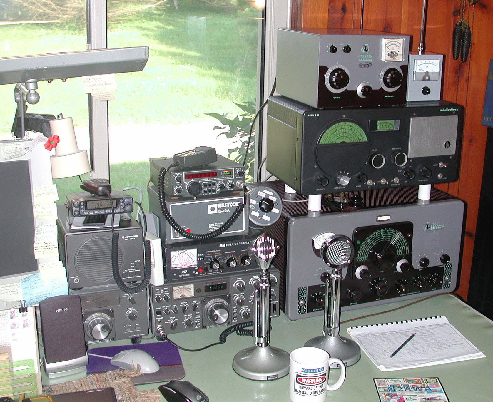
Amateur Radio Station - N2AWA / June 22, 2013
This photo was made to mark the occasion of adding the Johnson Viking Matchbox 250-23-3 tuner to the shack on June 15, 2013. A field strength meter (Lockport hamfest / $20 / 28-jan-2012) is sitting to the right of the tuner. The ICOM IC-260A VHF (2 meter) FM/SSB/CW Transceiver (added to the shack July 4, 2008) is also shown in this photo. Note the white, PVC "stand-offs" between the Johnson Viking Valiant transmitter and the Hallicrafters S-40 receiver, which were added to maximize the Valiant's ventilation. An R-48 telegraph key is sitting on top of the Valiant (under the S-40 receiver). The Yaesu FT-7800R 2m/70cm FM transceiver was moved to the top of the "SP-180" Kenwood speaker.
Antennas (HF)
November 2005 - Present:
Tuned, ½ wave, 20 meter dipole antenna inside the shack (MFJ 949E tuner position "COAX 1")December 2005 - October 2006:
For the Kenwood TS-530S HF rig I originally used a 100 foot (30 meter) random wire antenna. Used insulated, #22 AWG wire. Tuned up (with MFJ 949E Deluxe Versa Tuner II) on 80-75, 40, 30, and 20 meters. The wire snapped two times during the summer of 2006. Spliced it, and it kept working fine.Update 04-oct-2006:
Planned to upgrade the original #22 AWG random wire HF antenna to #14 AWG solid copper enameled wire. Needed about 125 feet. Also needed end insulators, stand-offs and 100 foot roll of 1/8" polyester antenna rope. Ordered most of the ingredients for the project on October 6, 2006 from Universal Radio. They had the "dog-bone" end insulators on back-order so to complete the order, I got the insulators through AES on October 25, 2006. They arrived via UPS Friday night October 27, 2006 so the project was able to move forward on the weekend of October 28-29, 2006.Preferred Weather Conditions for Installing a New Antenna
Update 29-oct-2006 (Sunday):
Erected a new "sky hook." This antenna is now history, but the following passage may be useful to those thinking about raising a new long-wire antenna.
Saturday was windy and "mild" (about 43º F [6º C]) and it rained heavily throughout the day. Sunday was a bit drier, but very windy, with clouds, and noticeably colder (about 25º F [-3º C]). There were also a few dozen snow flakes blowing around in all directions – just enough to make it a memorable experience. It was the season's first blast of winter air, and perfect for installing a new antenna! The long-standing joke (or perhaps truth) is that the best time to install a new antenna is during foul weather. That way, the planning and preparation is completed inside, and the out-of-doors work is carried out quickly. This is when one begins to ponder the advantages of indoor hobbies like stamp collecting.
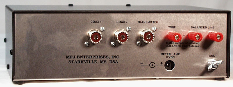
Tim (WB2PAY) helped install the 113 foot long (34 meter) #14 AWG solid copper enameled wire up about 15 feet (5 meters). Used 1/8 inch polyester antenna rope tied to "dog bone" end insulators secured to two trees. Back in the shack at the antenna tuner (MFJ-949E) on the "wire" connection jack, I used a spade lug crimped to the center conductor of RG8 coax. The coax was chosen (in theory) to reduce RF in the shack. The RG8 ran about 10 feet to a PVC pipe through the wall, and up to the gutter sill on the outside of the shack. At that point, the RG8 coax was fitted with a PL-259 connector. The PL-259 connector was screwed into an SO-239 connector (chassis mount - with no outer shell) on it. From there, the #14 AWG solid copper wire was soldered to the center pin of the SO-239. It was secured to a three-inch stand-off with two tie-wraps. Electrical tape and coax seal was wrapped around the connection to water-proof. From there, the wire headed south about 50 feet (15 meters) out to a White Ash. There was a "dog-bone" end insulator tied to the Ash with the antenna wire passing through the other hole of the insulator. From there, the antenna headed in a southwest direction for the final 75 feet (23 meters) out to an old apple tree. The wire was suspended by a second dog-bone end insulator tied to the apple tree. I got the antenna rope over the top of the apple tree by tying a 10 ounce fishing sinker to the end, and swinging the sinker, windmill-style, to give it the momentum and distance it needed to clear the top of the tree. It took a few attempts to get the correct release angle so the sinker sailed over the tree in just the right location. The antenna could be lowered by untying the antenna rope at either the White Ash or the apple tree. On Monday October 30, 2006 I took off from work and was able to break the pile-up and work V47NS on Nevis Island in the Caribbean (DX-pedition). Once he heard me, he turned his beam away from Europe and towards New York state. My RST was 59! I also heard Italy and England contacting him, but I did not try to contact them. Later that evening, I was also able to work two stations in Rochester, NY (Tim - WB2PAY on 75 meters and Carl - WA2GAI on 40 meters). This would not have been possible with the old long wire antenna, because Rochester was in the skip zone.Update 12-jan-2008:
Bargain on Pre-Enjoyed Coax
January 12, 2008: Purchased 53 m (175') of used Tandy RG8U coaxial cable in three separate sections. Outer jacket was in good condition. Included PL-259 connectors soldered on each end, and also two PL-258 "barrel" adapters (SO-239 to SO-239). The PL-258 connectors facilitate joining all three sections into a single section. To be used for testing various antenna configurations. Details, with retail prices (as of 12-jan-2008) are presented below. Item Retail value (per foot, or per unit) Total 15 m (50') RG8U coax $.79/ft $39.50 15 m (50') RG8U coax $.79/ft $39.50 22 m (75') RG8U coax $.79/ft $59.25 PL-259 (6) $2.19 $13.14 PL-258 (2) $1.99 $3.98 Total retail value $155.37 Total cost: $15.00 (10% of retail value) Update 22-jan-2008:
Started to think about designing or purchasing an 80 meter or multi-band dipole. Details here: antennas.txtAntenna Feed Line Entry Point To Shack
30-mar-2006:
Ran a section of ½ inch PVC tubing through the wall of the shack to the outside. Used a 45° elbow at the outside to prevent moisture from coming in. Sealed it up with calk and duct sealant (a.k.a. "monkey sh*t"). The ½ inch PVC is capable of passing three RG-8 cables, three RG-58 cables, and three #12 AWG ground wires. It has room to spare for a couple more cables or larger ground wires if needed.Hy-Power® 80 meter Dipole Antenna (commercially manufactured)
29-dec-2008:
Ordered a full sized (no coils) Hy-Power® 80 meter dipole antenna. The existing end-fed, random long wire antenna was difficult to tune on 3.837 MHz (the AWA AM Net frequency) and I could not fully load the wire with the Viking Valiant without getting some arcing inside the MFJ-949E antenna tuner. The arcing was causing audio distortion. See this link for details on the distorted audio saga. The ultimate solution was to get a Johnson Viking Matchbox 250-23-3 tuner for the Valiant.Description of the new 80 meter dipole antenna
Full-sized (no coils), full power dipole. Features #12 AWG UV insulated wire, uses stainless steel electrical hardware, an SO-239 center insulator, and two end insulators. The antenna was completely assembled and ready to install. Just added coaxial cable and nylon rope. Antenna length: 42 meters (138 feet).05-jan-2009:
The Hy-Power® 80 meter dipole antenna arrived.09-feb-2009:
Erected the Hy-Power® 80 meter dipole, and took the random long wire down. See details.
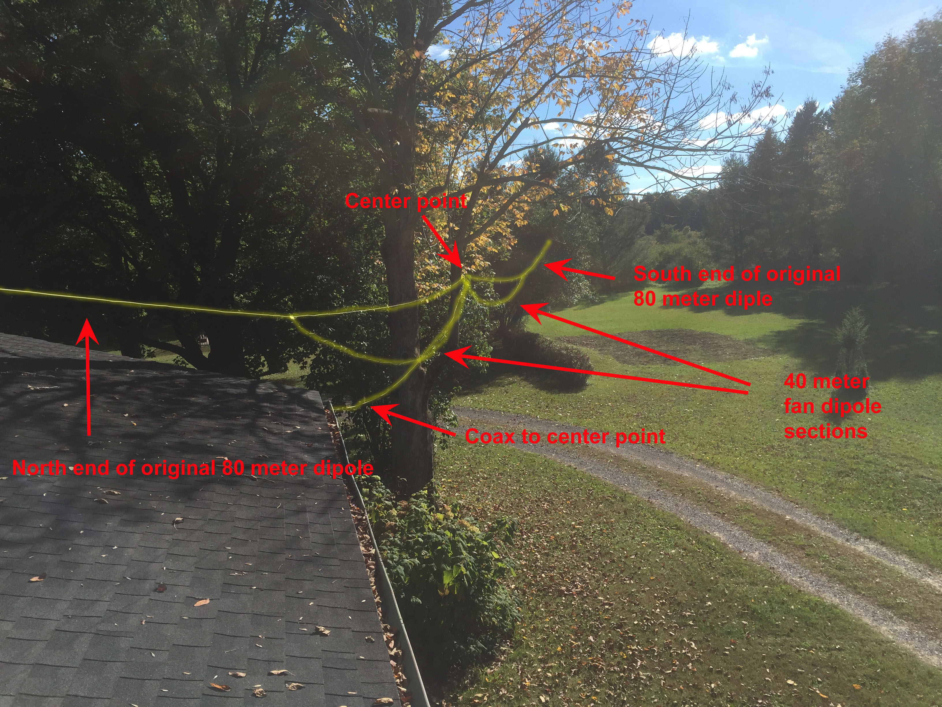
Fan Dipole Antenna for 80, 40, and 15 meters
September 29, 2015: Discovered I was unable to get out on 40 meters in the 7.100 - 7.200 MHz range with the Kenwood TS-530S and MFJ Versa Tuner II (MFJ-949E). Got the antenna books out, and did a little research on 40 meter "end-fed" wires, and found some pre-fab. solutions on eBay, but soon decided against any end-fed solution.
Solution 1 (abandoned – only for lack of readily available ladder line and a balun): Talked to Tim (WB2PAY) who suggested using "ladder line" to feed my 80 meter dipole instead of the 50 foot of coax. That solution would look like: Kenwood TS-530S transciever > MFJ Versa Tuner II (MFJ-949E) > coax to the outside and up under the eaves > to a 4:1 (or 1:1) balun > ladder line (50 foot to center support on tree) > to the existing 80 meter dipole. This solution requires lowering the center point of the existing 80 meter antenna, but does not require changing the 80 meter dipole wires.
October 3, 2015 (Saturday): Solution 2 (Adopted): Tim came over at 1:40 p.m. and we built a 40 meter, half-wave "fan dipole" antenna. WX conditions were cloudy and 52° with sparse rain sprinkles that looked eerily like snow. First, a bit of insulation was stripped from each side of the existing #12 AWG 80 meter dipole where it was supported at the center. Then soldered two new separate, insulated (black) #12 AWG wires from the center point of the existing 80 meter dipole. Ran the #12 AWG wire out 33 feet* in each direction beneath (and in parallel with) the 80 meter dipole, and terminated them at the ends with ceramic insulators, Dacron rope, and tie-wraps. Reference the photos.
*Formula: "468 / freq. (MHz) = total length for 1/2 wave horizontal dipole"
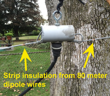
Step 1. Making a 40 meter "fan dipole" antenna: Lowered the center point (where coax connects), and the south end of the existing Hy-Power® 80 meter dipole (erected 09-feb-2009). Then stripped some of the gray insulation from the existing 80 meter dipole wires near the center connector. See photo.
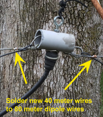
Step 2: Looped the new #12 AWG gauge 40 meter dipole wires around the ends of the existing 80 meter dipole wires (creating a strain relief), and then soldered the ends of the new 40 meter wires to the points on the 80 meter wires that were just stripped of insulation. Wrapped the solder joints with electrical tape to prevent oxidation.
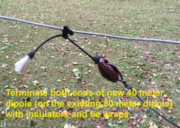
Step 3: Ran the new 40 meter antenna wires out 33 feet in each direction in parallel with the existing 80 meter dipole. Let the new 40 meter wires droop a little in the middle. Terminated both ends of the new 40 meter antenna with ceramic "egg" insulators, Dacron rope and tie-wraps.
Finally: Raised the center and south end of the new fan dipole up to its normal operating height, and went inside the shack to load it up. With the help of the MFJ 949E tuner, it tuned up fine on 80, 40, and 15 meters. In fact, I worked my first-ever "6 Land" station (California) on 15 meters (N6PEQ) during the California QSO party. I was his 315th contact, and he was my number 1 contact "for the log" – although this text is the only logging made on my end. Total project time was about 90 minutes.
40 meter "fan dipole" antenna (unannotated / annotated) / October 10, 2015 / Camera: iPhone 6
New 80 meter Dipole Centerpoint
The old White Ash, which was being used as the centerpoint of the 80 meter dipole was attacked by the fatal emerald ash borer and unfortunately needed to be taken down.
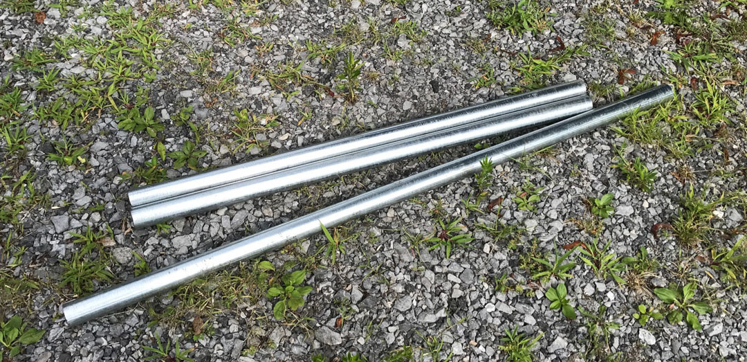
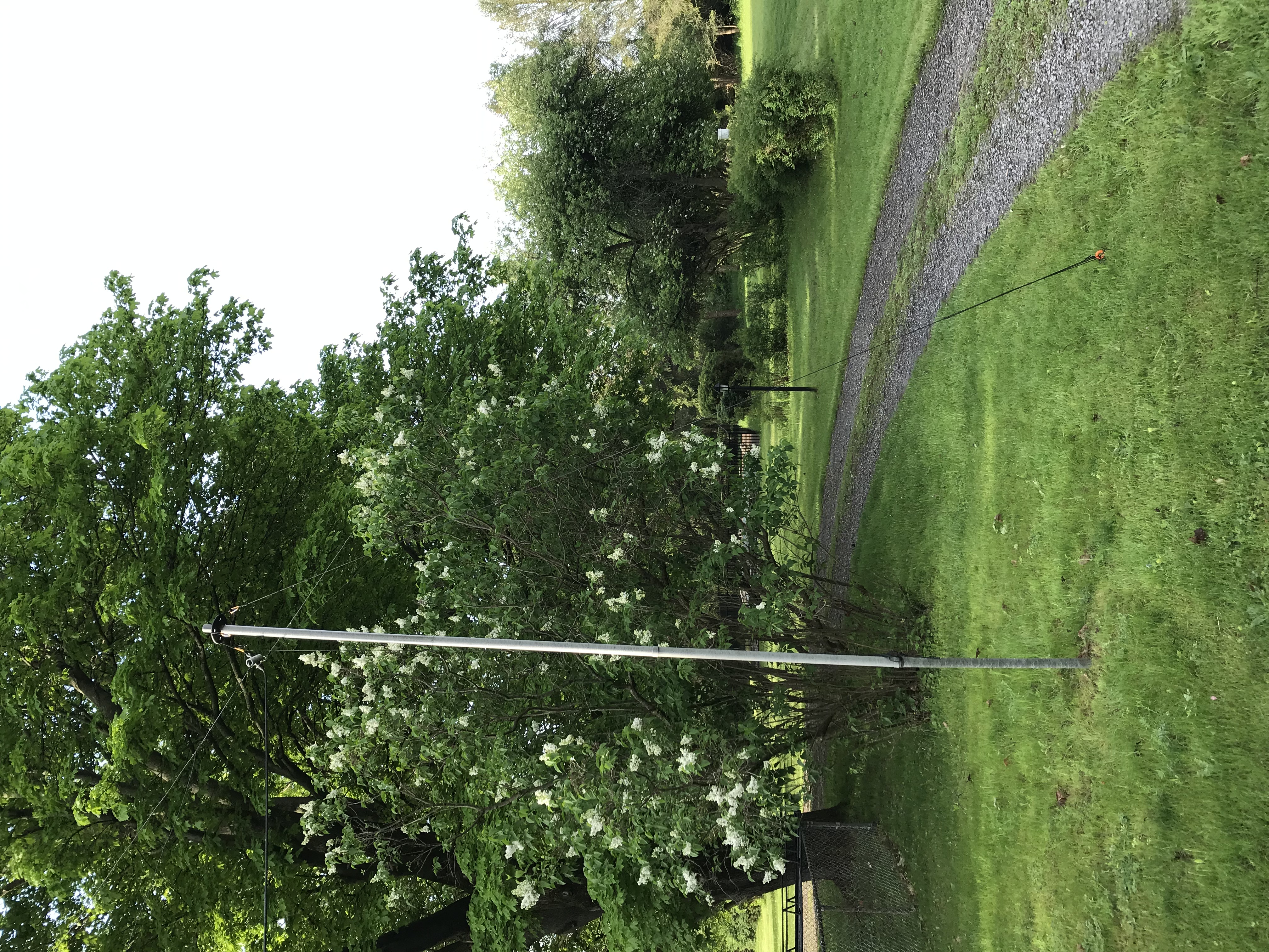
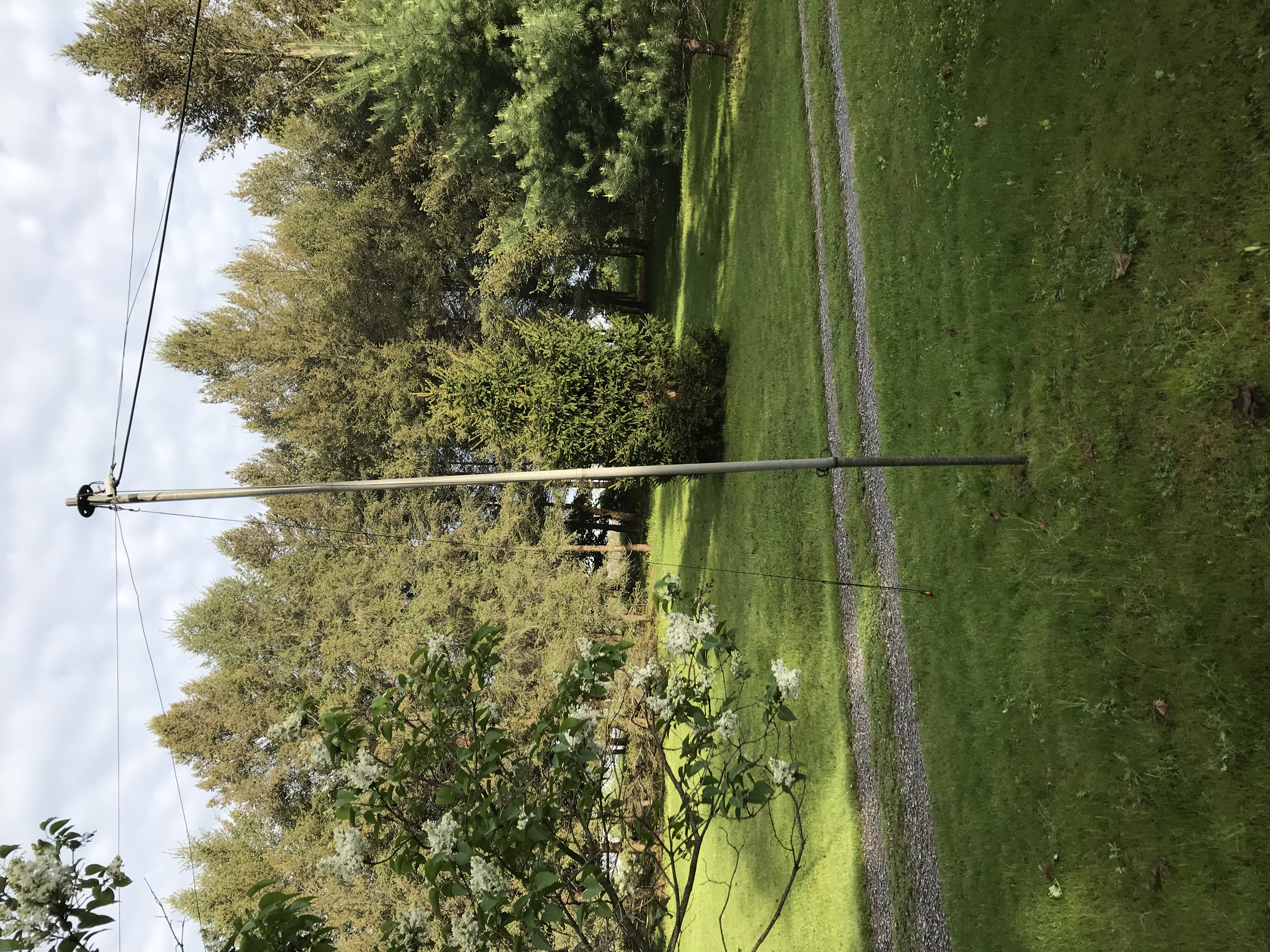
July 21, 2017 (Friday): Tim (WB2PAY) graciously supplied four, 4-foot, inter-connecting, olive drab poles, a top ring, a four-footed, adjustible base, and three D-clips (a.k.a. carabiner clips) (affixed to the top ring for guy ropes – see photo) to create a new, free-standing centerpoint support for the 80 meter dipole. Used two sand bags on the base to serve as stabilizers until the tree was removed. When it was removed, a four foot piece of electrical conduit (1½" o.d.) was pounded into the ground to replace the base and sand bags.
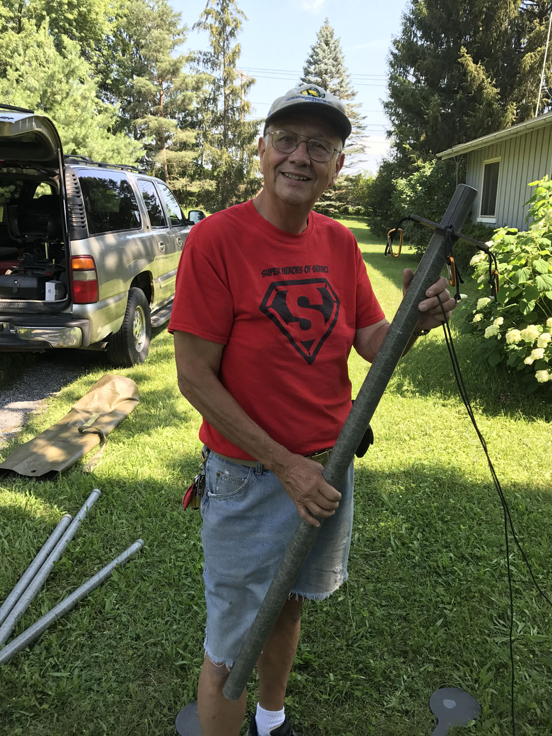
July 21, 2017: Tim (WB2PAY) with the free-standing center support pole for the 80 meter dipole antenna. The conduit (see photo) was obtained a few days later at Debbie Supply in East Rochester, and they cut it so there was at least one four foot section. / Camera: iPhone 7
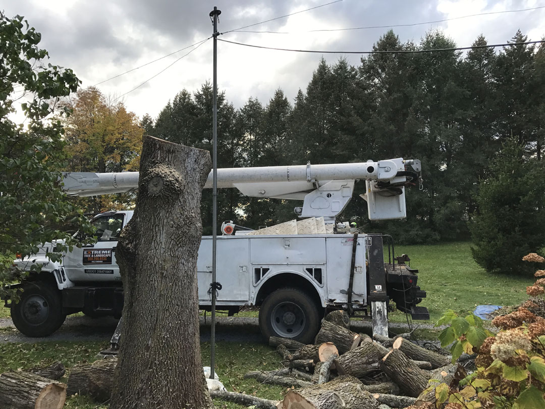
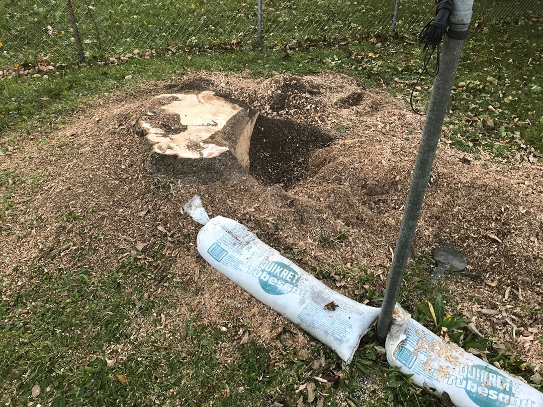
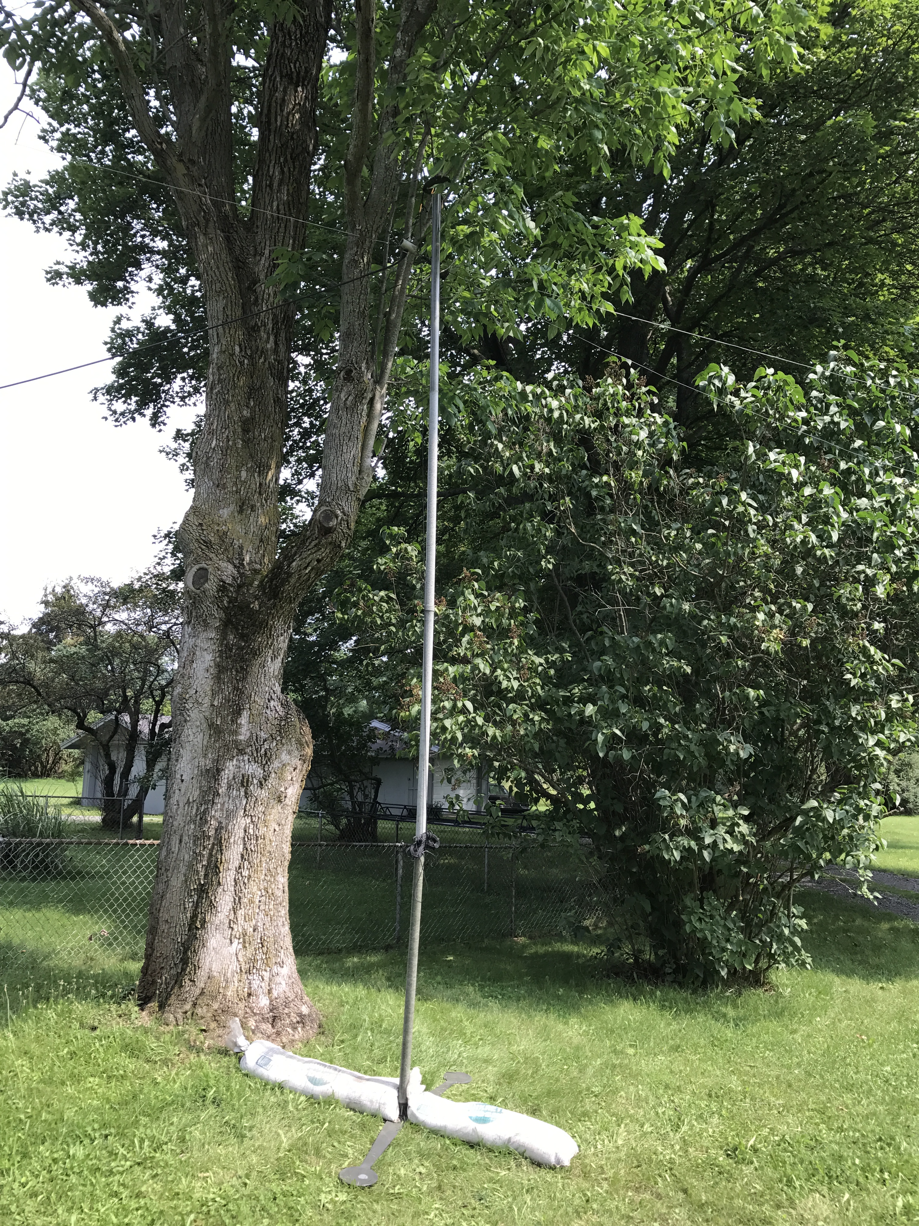
The White Ash finally came down October 24, and the stump grinding was completed the following Monday. Note the sand bags laying on two of the adjustable base feet. The weight was used to ensure the bottom of the mast would not kick out. Having sat out in the elements for over three months, and especially after the tree and stump removal, they naturally looked a little worse for wear when they were placed back into storage. A big "shout out" to the crew of Extreme Tree and Landscape for skillfully working around the pole, antenna wires, and sand bags.
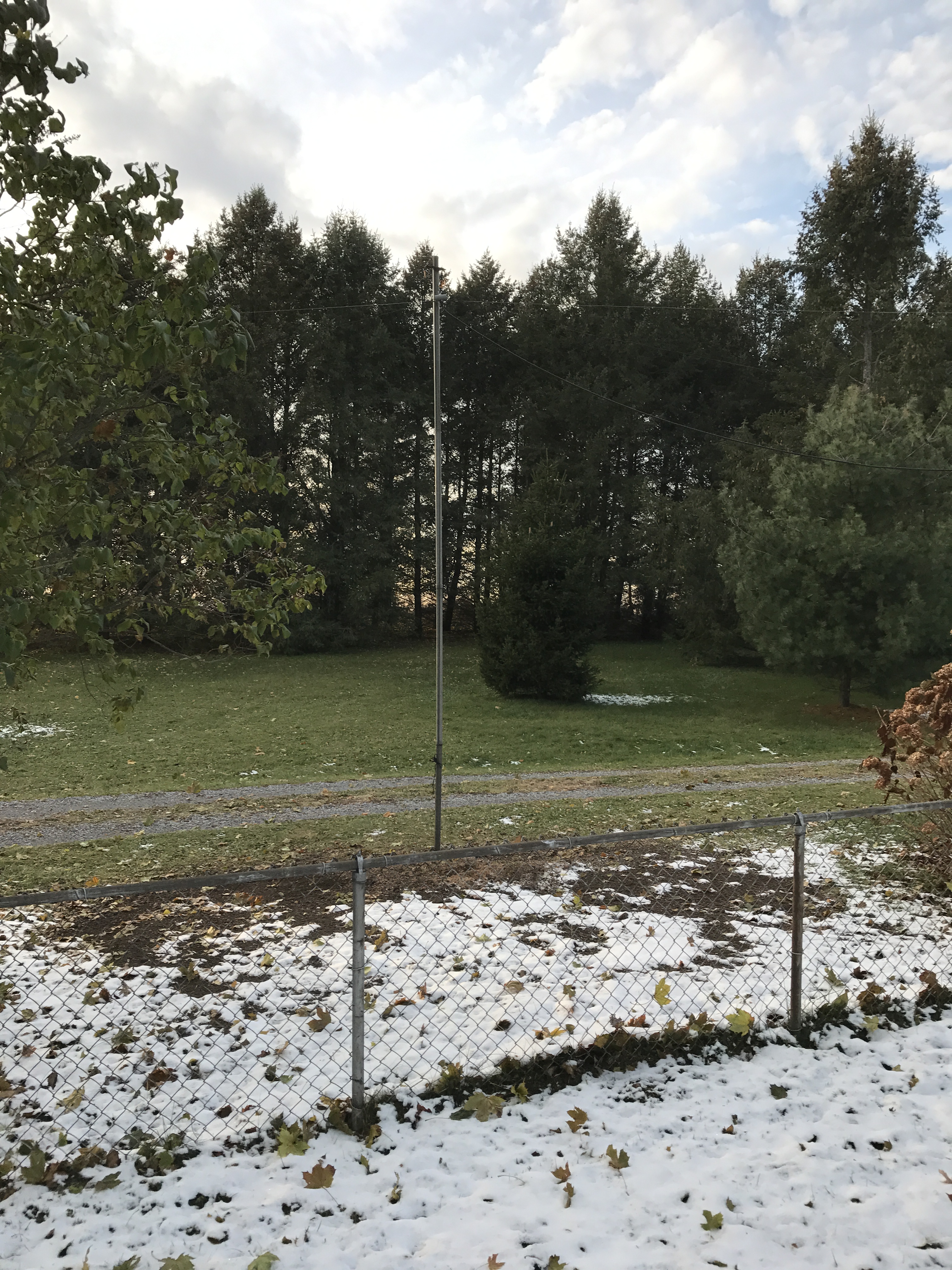
November 11, 2017 (Saturday): It was 22° – supposedly "good weather for doing antenna work." The theory is that as it gets colder, the more it makes sense to plan everything in advance and get the work done quickly. Note: what appears to be white sand (see photo) is actually the remnants of the season's first snow fall.
Pounded the four foot section of electrical conduit (1½" o.d.) into the ground, and slid the first mast section over it. Aligned it as straight as possible, and placed the other three inter-connecting poles on top of that. Pulled the Dacron UV resistant rope tight to raise the coax, top ring, etc. Tied a "clove hitch" to secure the rope to the mast (see photo) and cut off the excess rope – leaving enough slack to lower the wires if needed. Set the base and sand bags aside, and raked out the remaining wood chips. Tested the antenna at 6:00 p.m. with the Kenwood TS-530S on 3.922 MHz with Tim (WB2PAY) and he copied me at an S7. It took four months to get the tree removed, but the project was completed before the arrival of winter.
Update May 12, 2019 (Sunday):
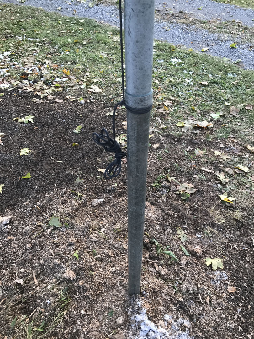
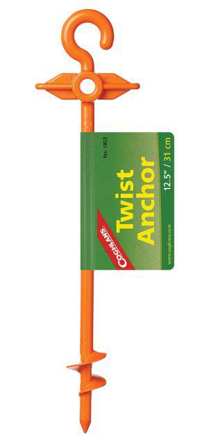
Got four "utility anchors" (a.k.a. tent pegs) for $1.48 each at Walmart (Ithaca, NY).May 22, 2019 (Wednesday):
Atmospheric antenna work conditions: overcast with a mass of dark clouds, and temp. about 67°. Repurposed some pre-enjoyed Dacron UV resistant rope to guy the pole, as it had begun leaning to the east. At the top, used one of three D-clips (a.k.a. carabiner clips) (affixed to the top ring in July 2017 specifically for guy ropes – see photo). At the bottom, used one of the tent pegs to anchor the rope into the ground. Tim (WB2PAY) dropped by on Wednesday May 22 (5:21 p.m.) to oversee the knot tieing (it's a Boy Scout thing). Enjoyed a good eyeball QSO as we had not done since November 2017.
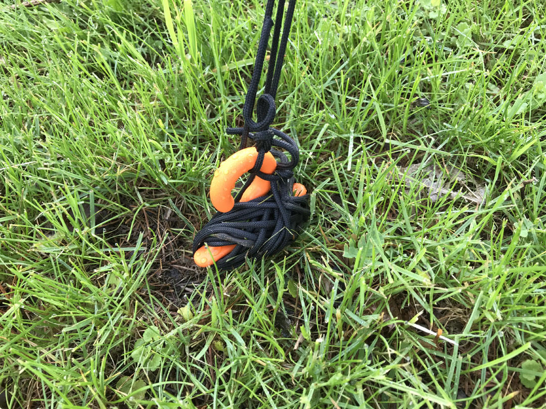
L to R: "utility anchor" (a.k.a. tent pole), looking south, looking west, tent pole
in ground
Photos taken/uploaded May 23, 2019 / iPhone 7
We also examined and pondered the 80 meter dipole's north support rope, which had broken sometime over the winter (discovered while cutting the lawn). Mysteriously, even though the section of Dacron rope that was fed through a ceramic insulator (mounted high up in the tall pine tree) had broken, somehow tension remained, and the antenna was fully elevated. Upon closer inspection, the pulley could be seen hanging loose (up about 12 feet – in the midst of twisted branches and twigs in the middle of the tree), along with the other end of the frayed rope. When it snapped, the section between the dog bone insulator (in the air) and the ballast bucket (on the ground) must have remained supported by a branch. Lifting the ballast bucket off the ground lowered the antenna accordingly, so there was still free movement between the remaining parts. No further action was taken. Tim set sail around 6:55 p.m. just as it started to sprinkle.
How Antenna Tuners Work
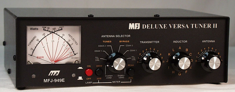
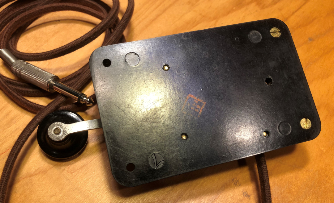
MFJ Deluxe Versa Tuner II (MFJ-949E) 300 Watt antenna tuner.
$40.00 / used / Horseheads, NY Winter Hamfest / February 25, 2006 / Sold new (as of fall / winter 2005) for $140-$150. As of December 2008, it listed for $179 ($189 / June 2013).MFJ Product Information
www.mfjenterprises.com/Product.php?productid=MFJ-949E
MFJ Deluxe Versa Tuner II (MFJ-949E) 300 Watt Antenna Tuner |
||
 |
 |
 |
The MFJ-949E SWR/Wattmeter can be illuminated with 12 Vdc. Reference part number: MFJ-1312C. This is an AC "wall wart" transformer with a 2.5* mm coaxial plug with a positive center pin polarity (according to the MFJ .pdf file). Carey (K2RNY) verified the 2.5 mm plug did not fit.
*The MFJ website listed a different part number, and slightly smaller plug size – p/n: MFJ-1312D, 12 Vdc, 500 mA AC adapter with 2.1 mm jack with positive center pin polarity. This plug size was correct.
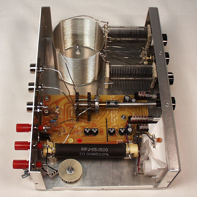
Reference photo – the faulty MFJ 949E transmitter tuning capacitor. Notice the off-center spacing between the plates. This was probably a manufacturing defect. A new capacitor was sourced from MFJ (for a fee).
15-mar-2009:
Discovered the MFJ 949E tuner was arcing when used with the Viking Valiant AM transmitter. The "transmitter" tuning capacitor (left side) appeared to have a manufacturing defect – the plates were not centered (see photo). Ordered a replacement from MFJ; part number: 282-2005 ($23.85 + $4.00 shipping). A representative from the technical department later claimed (via email) he would have shipped the part for free.21-mar-2009:
Replaced the tuning capacitor in the MFJ 949E and the arching problem ceased to exist.
MFJ Deluxe Versa Tuner II (MFJ-949E) Settings
- Used with the Kenwood TS-530S transceiver.
- Antennas: 80 meter dipole, 40 meter dipole, 20 meter dipole
- Ground system: Two ground rods (4' galvanized and 8' copper) wired to each other directly outside the shack, approximately 70 mm (2.5") apart.
Odd Harmonic Resonance
Antennas will resonate on odd harmonics (odd multiples of the resonant [first harmonic] frequency).
Examples
- Assume the frequency is 3.620 MHz on 80 meters. An 80 meter dipole at 3.620 MHz will resonate at 5*3.620 = 18.1 MHz (17 meter band). Note that the third harmonic of 3.620 (10.86 MHz) does not fall into a ham band.
- Assume 40 meter dipole where frequency is 7.126. This antenna will resonate on 15 meters (3*7.126 MHz = 21.378 MHz).
"band"
(on transceiver or transmitter)Photo "transmitter" switch
(on MFJ-949E tuner)"inductor" switch
(on MFJ-949E tuner) A=least inductance, L=max. inductance"antenna" switch
(on MFJ-949E tuner)160 m (1800 - 2000 kHz) TBD TBD TBD 80 m (3500 - 3750 kHz)
75 m (3750-5000 kHz)6.9 C 5 o-clock position
(off scale as of 09-jan-2018)
Knob needs adjustment!60 m (5330.5 - 5403.5 kHz) TBD TBD TBD 40 m (7000 - 7300 kHz) TBD TBD TBD 30 m (1010 - 1015 kHz) TBD TBD TBD 20 m (14,000 - 14, 350 kHz) TBD TBD TBD 17 m (18068 - 18168 kHz) TBD TBD TBD 15 m (21,000 - 21,450 kHz) TBD TBD TBD 12 m (24890 - 24990 kHz) TBD TBD TBD 10 m (28000 - 29700 kHz) TBD TBD TBD
Photos: June 19, 2013 / Nikon Coolpix 990
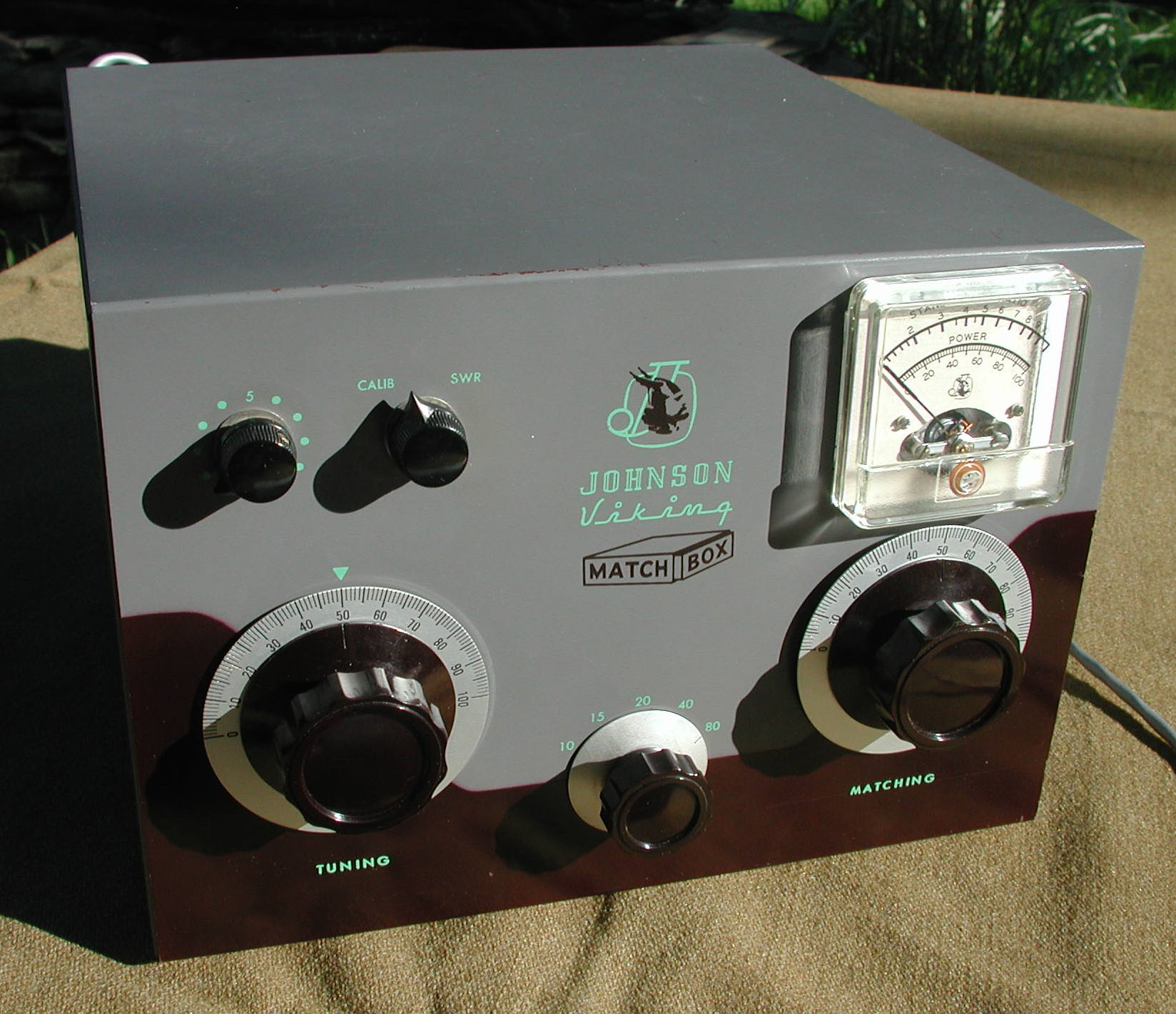
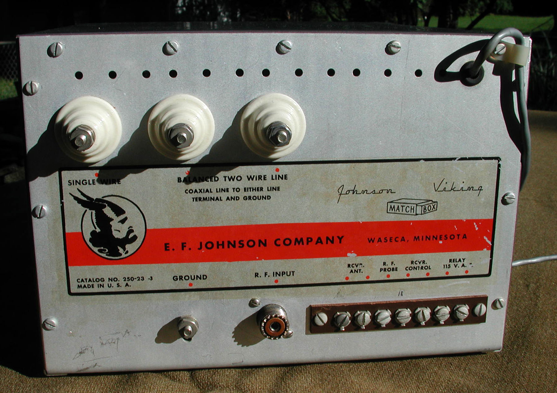
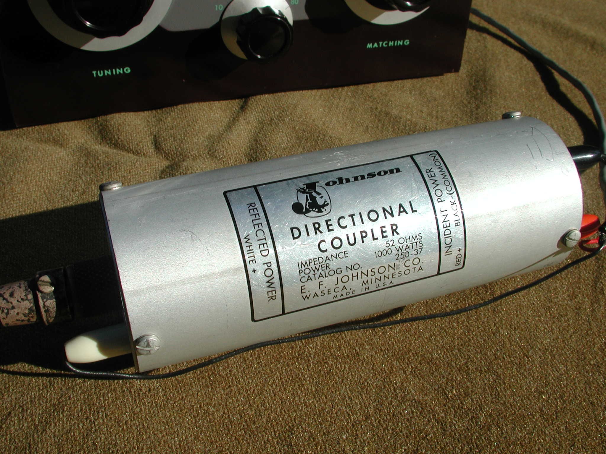
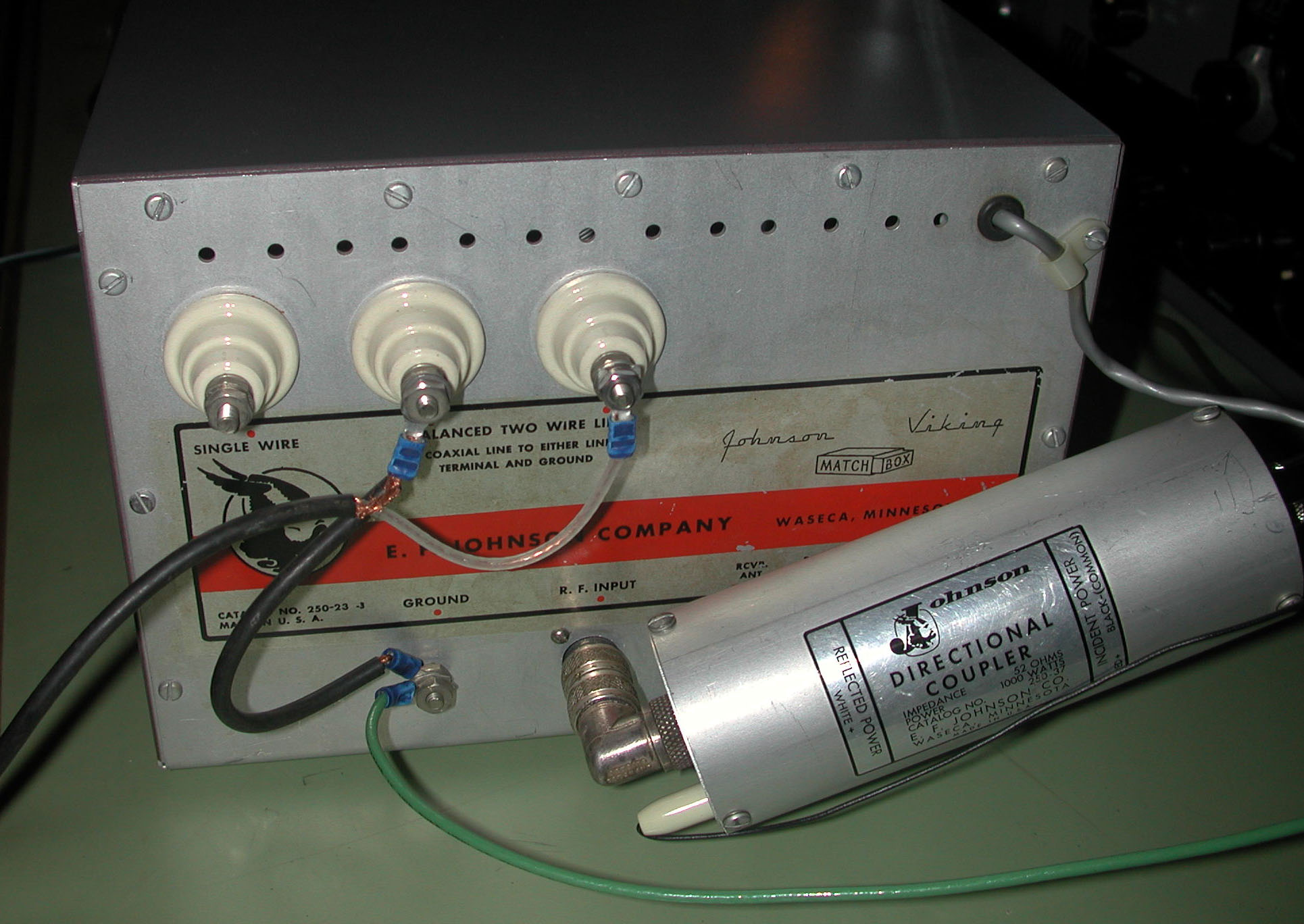
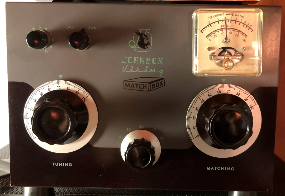
Johnson Viking Matchbox Model 250-23-3 (with meter) and remote directional coupler (Johnson p/n 250-37)
Allied Radio Catalog No. 170 1958 – describing Matchbox model "250-23" (without SWR meter)...
"Performs all transmission line matching and switching functions required in low or medium-power stations. For the 80-10 meter Amateur bands. Matches balanced antennas from 25 to 1200 ohms and unbalanced or single wire antennas from 25 to 3000 ohms. Nominal input impedance 52 ohms, rated at 275 watts. Built-in transmit-receive relay. Has adjustment for matching antenna to receiver. Coaxial input and 7-terminal receiver and relay strip. Maroon and gray metal cabinet. 9 7/8 x 10 1/2 x 7", Shpg. wt., 11 lbs. $54.95"
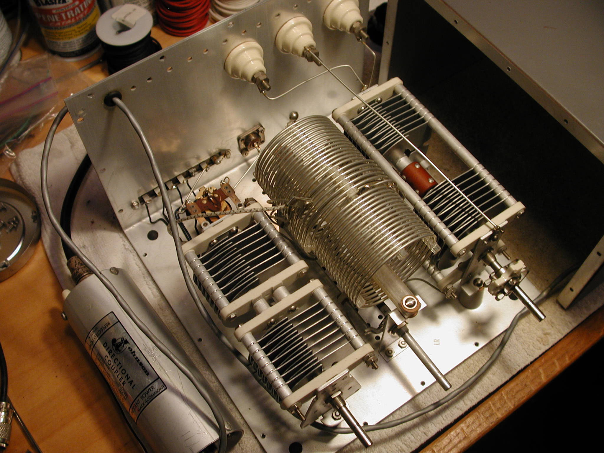
15-jun-2013:
Found this antenna tuner at the Rochester Hamfest. It included the directional coupler, and the original manual (in the original Johnson envelope [with logo]). Price was $100, and condition was described as "untested."All connection studs (including ground) were #10. The unit as missing one #10 nut, and two #10 washers. Only needed to fabricate a short coax jumper to run between the antenna switch (a.k.a. TR switch, or "Dow Key Relay") and the two ceramic, "balanced line" terminals at the back of the unit. The Matchbox tuner includes a built-in transmit/receive relay, but I already employed a "TR switch" powered by the Viking Valiant transmitter, so the Matchbox's internal relay was not needed. Tim (WB2PAY) graciously made the three foot jumper, which included a six inch run of braided shield for the ground connection, and provided the missing hardware.
18-jun-2013:
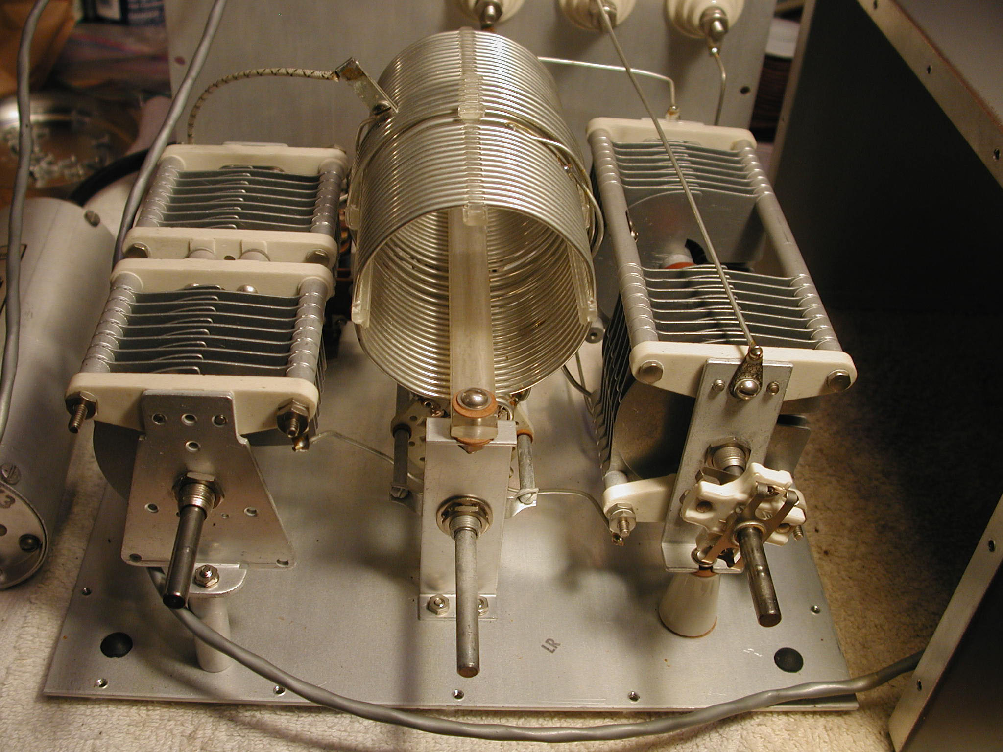
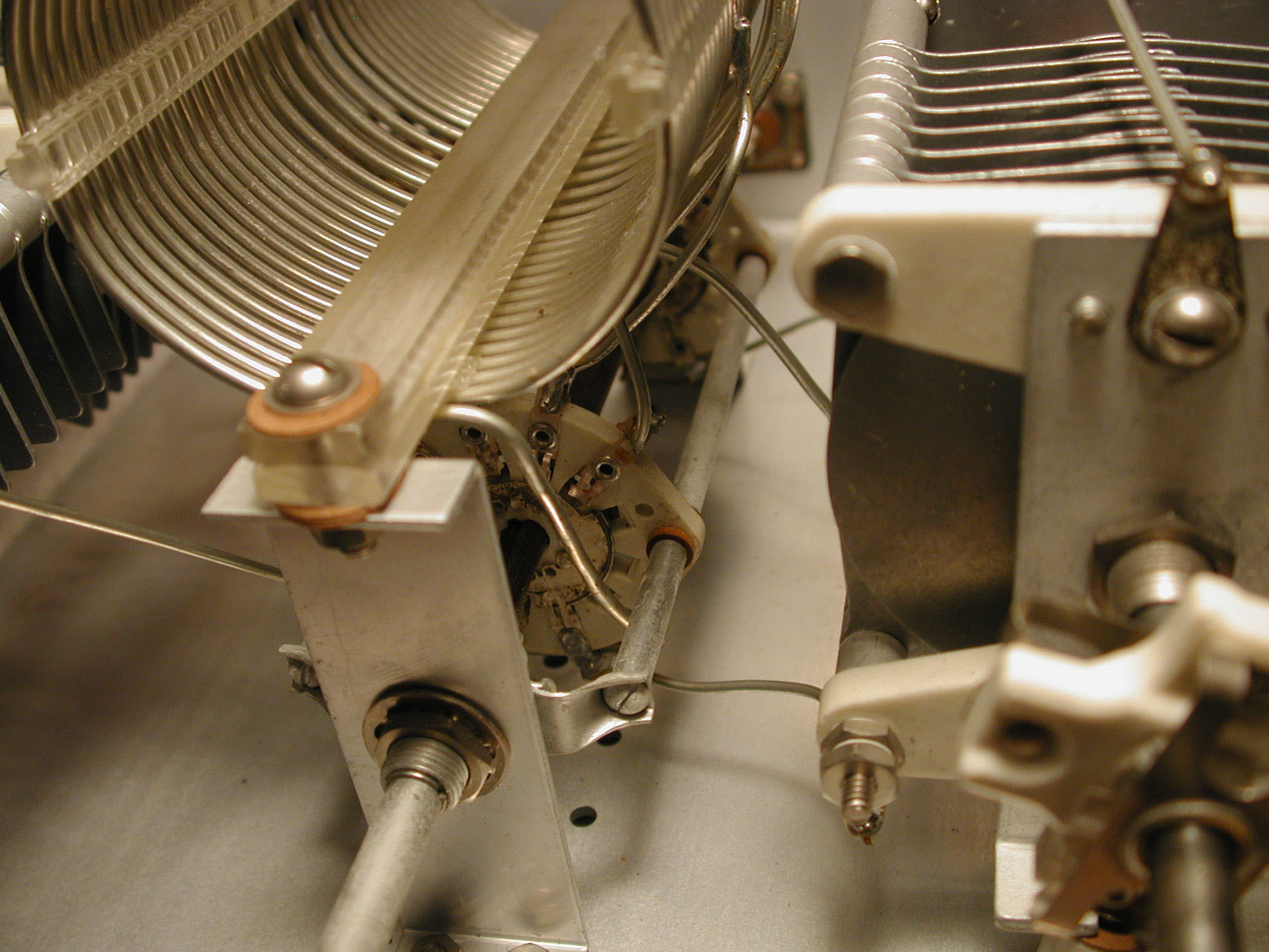
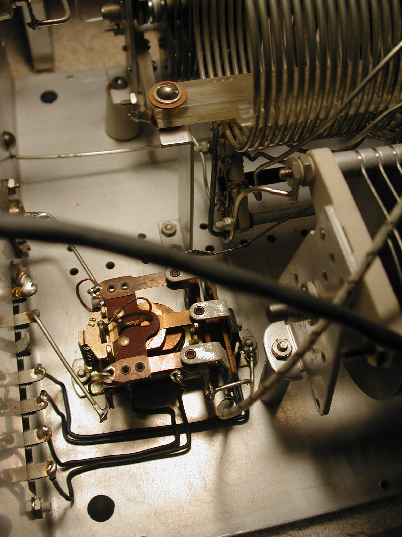
Installed the tuner in the shack, and had plenty of forward power meter deflection (calibrate mode), but in SWR mode, the meter was not adjustable with the tuning and matching knobs. Opened up the tuner (see photos) and everything appeared to be pristine. Suspected a bad diode in the directional coupler (the separate canister).
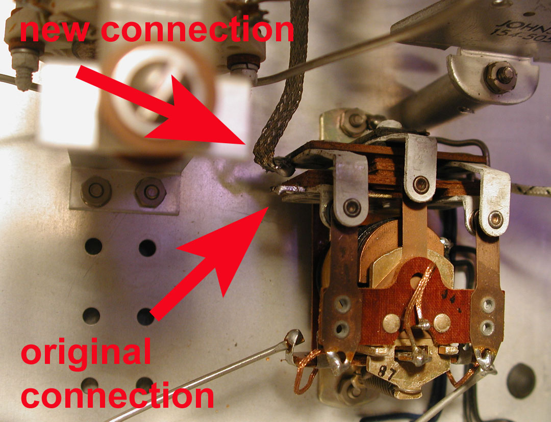
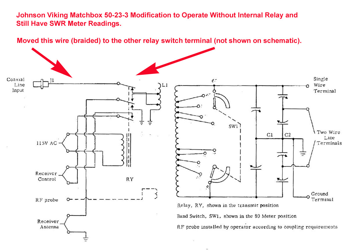
Matchbox relay circuit modification to enable operation without the relay, and still obtain SWR meter readings while adjusting the "tuning" and "matching" capacitors.
20-jun-2013:
Tim visited again – prepared to replace the coupler diodes, which were suspected bad. Both diodes measured fine (0.3 Ω in one direction, and infinite Ω in the other). Then removed the 22 sheet-metal screws from the cabinet (and Daka Ware band switch and tuning knobs), and discovered the relay was wired (presumably at the factory) so the antenna was out of the circuit unless/until the relay was energized.Searched online for "Johnson Matchbox relay circuit" and found others with the same concerns and questions. Some people reported finding bits of paper and/or cardboard jamming the relay closed, etc. We checked various continuity points between the relay and external connections on the cabinet, and studied the schematic and decided to move (un-solder) one wire (braided) and solder it to the opposing relay switch contact (reference photo).
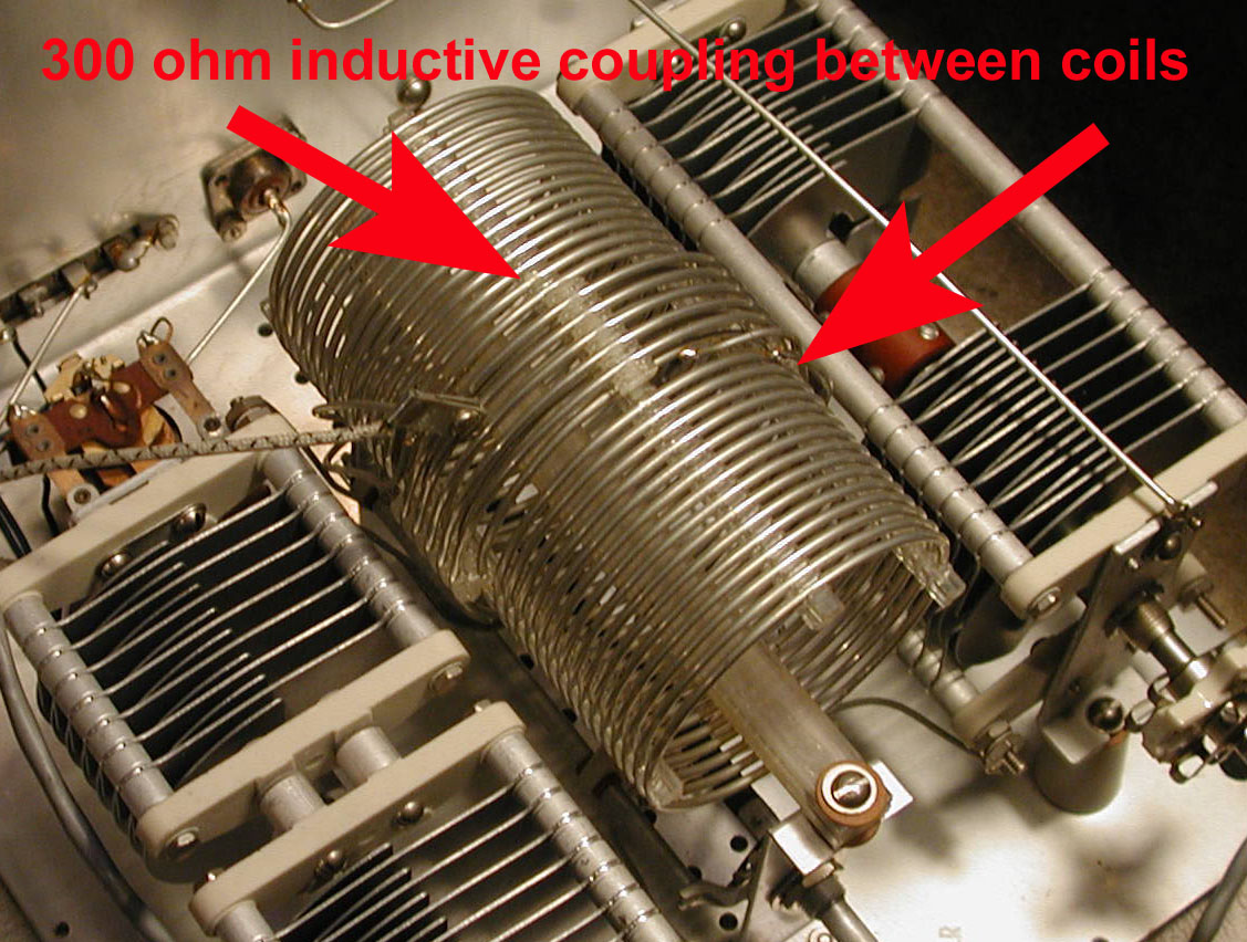
After modifying the relay circuit, we tested the tuner again, but Tim's MFJ model 259B (HF and VHF [no UHF]) SWR analyzer was incapable of driving the 300 Ω inductive coupling between the coils, so it "appeared" to still have a problem, i.e. adjusting the tuning knobs did not change the SWR on the MFJ analyzer. Hooked the Matchbox up to the Viking Valiant transmitter and was finally able to get the meter working in SWR mode – SUCCESS! The built-in Matchbox relay is a nice feature for switching the antenna between the transmitter and receiver, but I was already using a "Dow Key Relay" for the same purpose, so this feature would be useful if one did not have another way to switch the antenna between the transmitter and receiver.
19-oct-2020:
Tune the Viking Valiant transmitter into a Heathkit Cantenna (50 Ω dummy load).
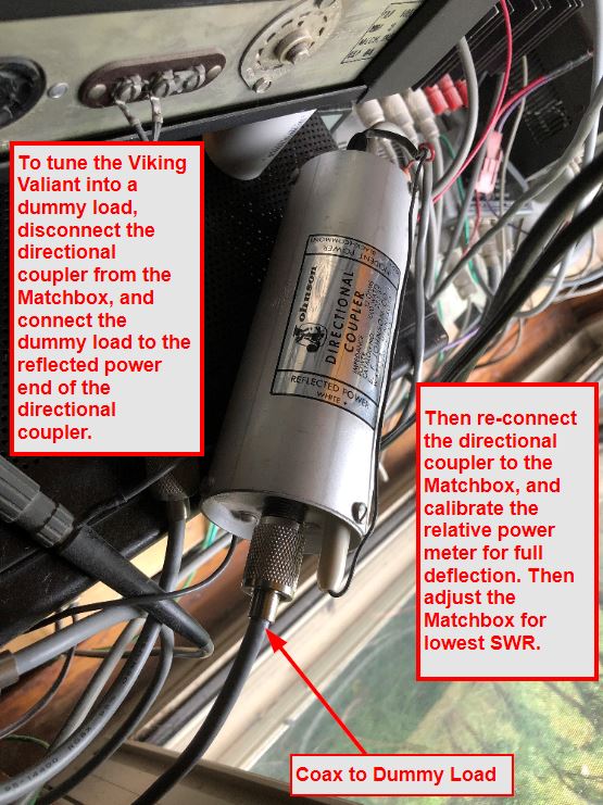
Until another 2-pole coax switch arrived, this was the manual procedure for connecting the Viking Valiant transmitter to a Heathkit Cantenna (50 Ω dummy load) for tuning purposes.
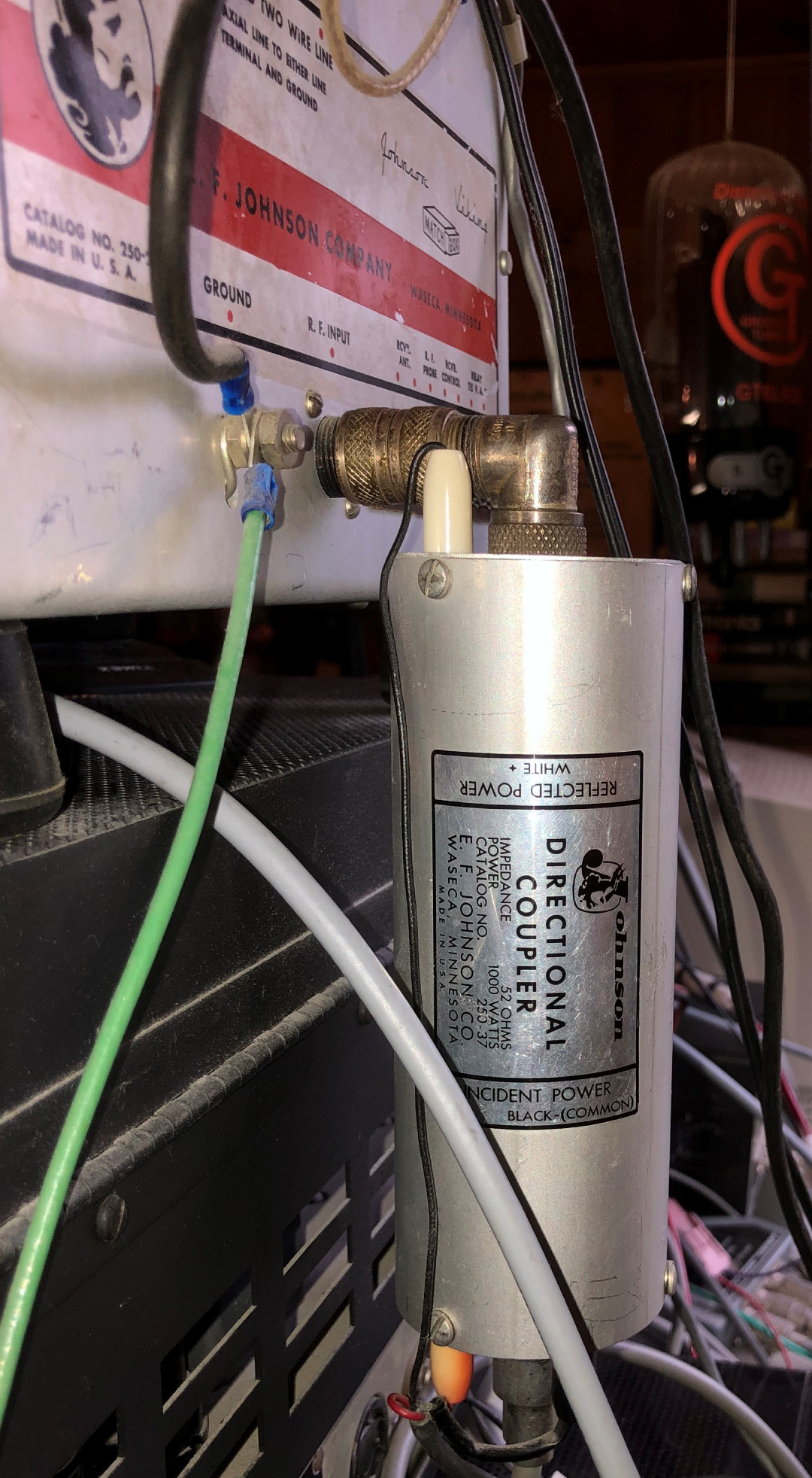
- Disconnect the Johnson "directional coupler" from the "R.F. Input" of the Johnson Viking Matchbox.
- Connect the 50 Ω dummy load to the "reflected power" end of the directional coupler.
- Follow the tuning instructions in the Viking Valiant Transmitter Operating Manual. Note: Tuning Procedure begins on p.13 (p.19 of the PDF).
- Once the transmitter is tuned up into the dummy load, then re-connect the directional coupler to the Johnson Viking Matchbox.
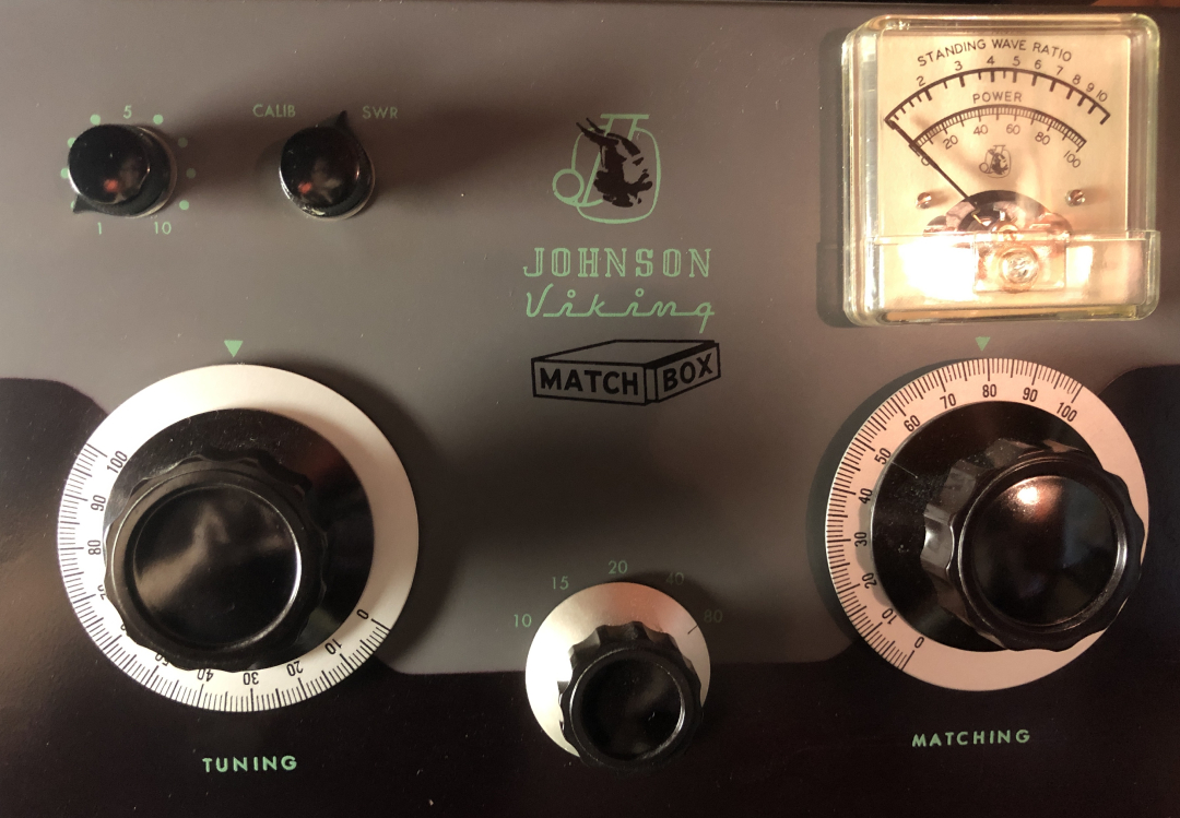
- Use the "CALIB" (i.e. "forward power") switch on the front of the Matchbox to calibrate (i.e. set) the full relative power meter deflection.
- Finally, select the correct band of operation (center dial on the Matchbox), and adjust the Matchbox "tuning" and "matching" dials for the lowest SWR.
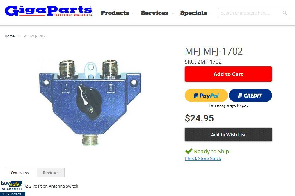
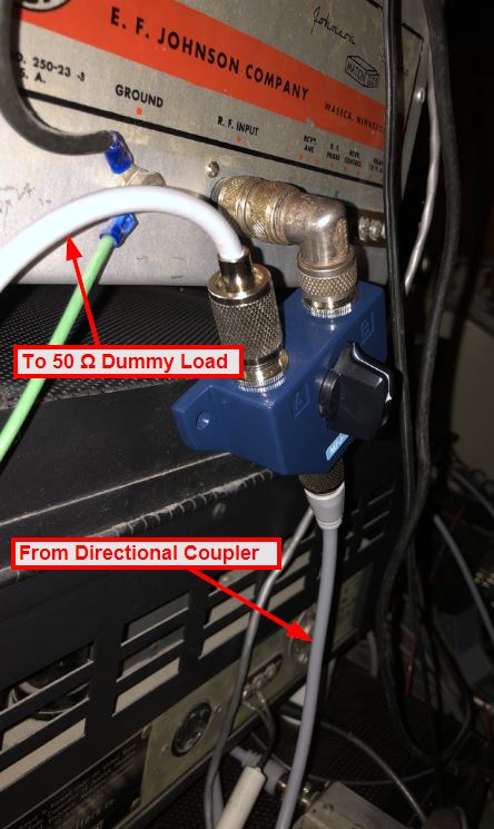
19-oct-2020: Ordered a 2-pole coax switch from Gigaparts (MFJ-1702). Connected the center tap of the switch to the "reflected power" end of the directional coupler. This provided the ability to quickly switch between the directional coupler (the transmitter output) and the 50 Ω dummy load.
For Sanity: switching the 50 Ω dummy load into the circuit bypasses the Viking Matchbox, so its "tuning" and "matching" dials (on the front panel) have no effect on the SWR meter reading, which should be a perfect 1:1 match, and yield no SWR meter deflection.
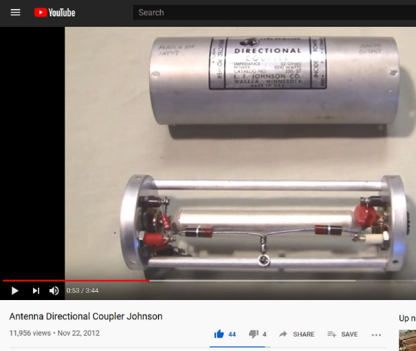
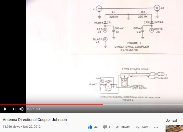
23-oct-2020: Screen captures from YouTube video showing the inside, and schematic diagram of the Johnson Viking directional coupler.
|
||
 |
 |
 |
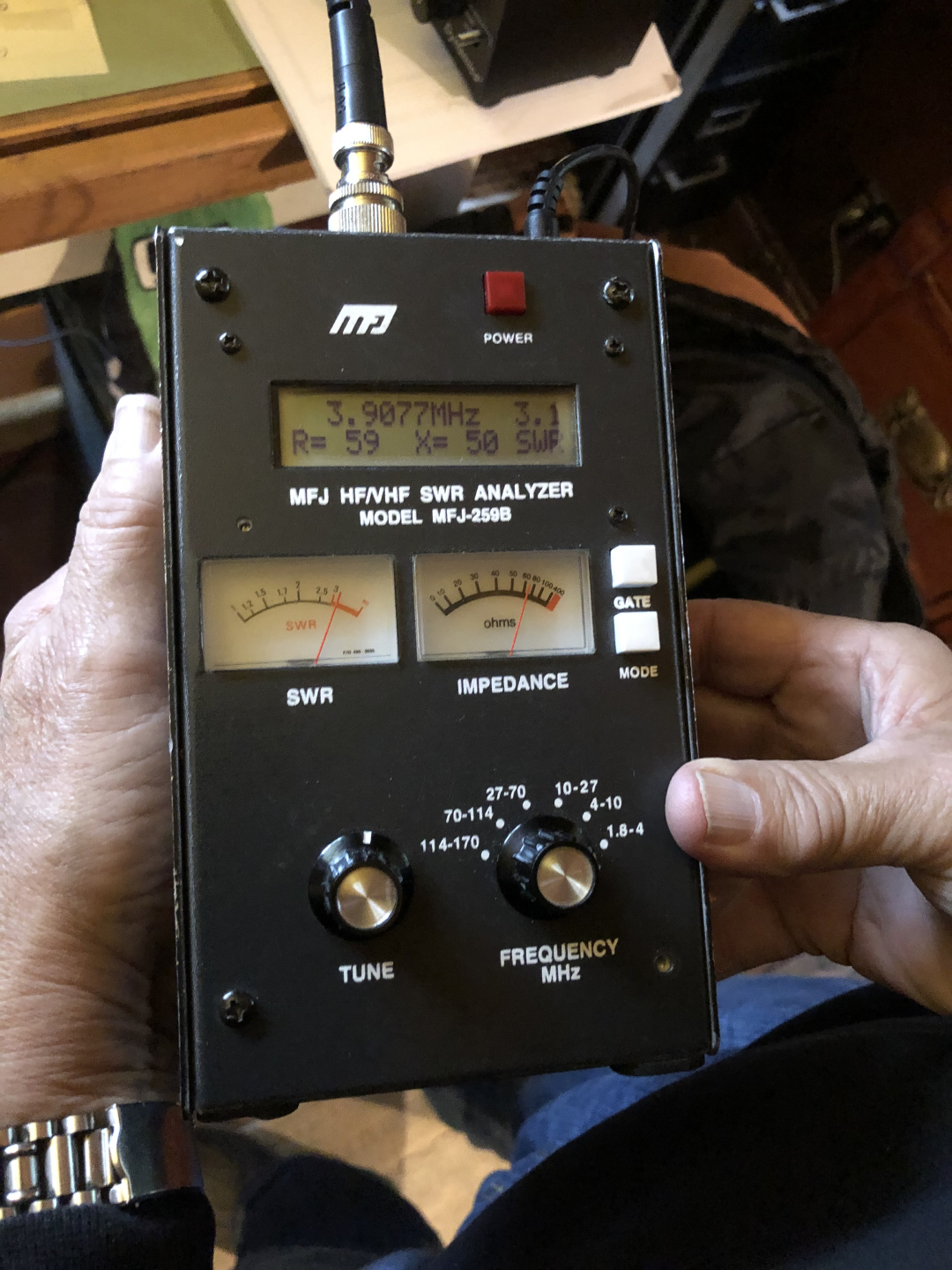
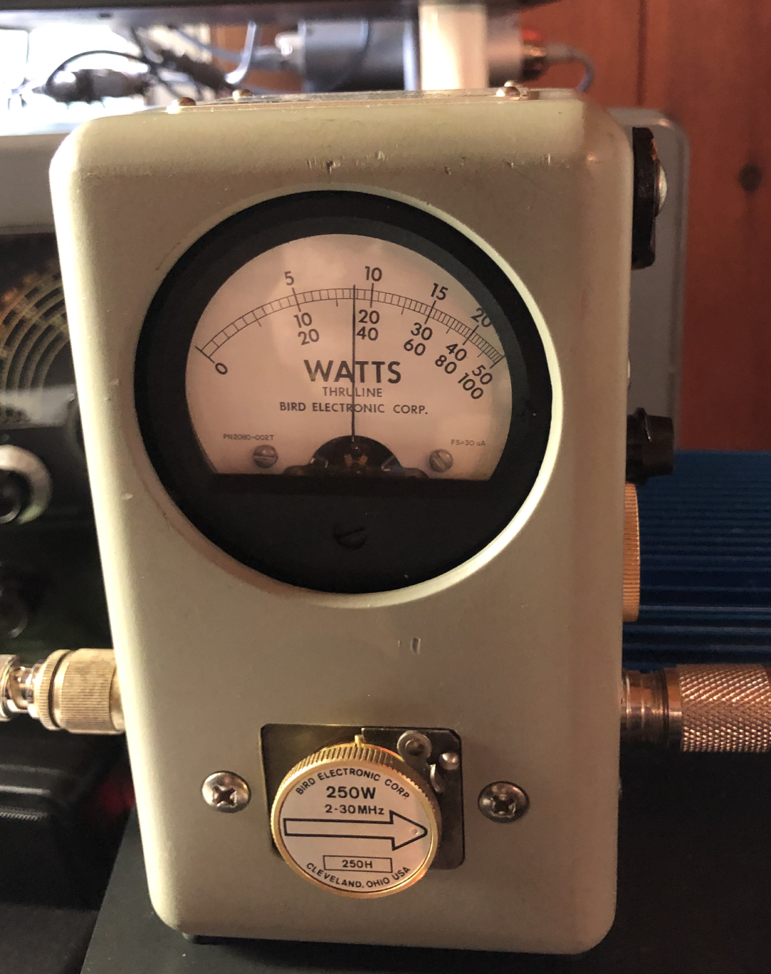
| Calculate 80 m dipole SWR with MFJ 259B analyzer. Result: 1.8:1 (not shown in photo). | Measure tuned-up Viking Valiant output power with Bird (model 43) wattmeter. | Notice the Johnson Matchbox "tuning" and "matching" dial settings for reference. The SWR reading is inaccurate – it's actually 1:8:1. The false reading may be due to coax being connected to the balanced line terminals. |
26-oct-2020: Tim (WB2PAY) used his MFJ model 259B (HF and VHF [no UHF]) SWR analyzer to determine the SWR of the 80 meter dipole was about 1.8:1. The SWR reading on the Matchbox was found to be inaccurate (it read 3:1) – likely due to having the antenna coax hooked up to the balanced line connections on the Matchbox. Tim also placed his Thruline Bird (model 43) wattmeter in-line to double-check the antenna SWR, and got the same results. Power out of the Valiant measured about 90 watts with about 5 watts reflected. Also placed a Micronta "field strength / SWR tester" in-line, and came up with the same 1.8:1 SWR reading.
28-oct-2020: Tim suggested that since 90 watts out of the Valiant was a bit low (110 - 120 watts is more typical) that the three 6146 "parallel final amplifier" tubes and the 5763 "RF Multiplier/Driver" tube may be getting weak due to age. Note: 90 watts is 75% of the "more typical" output (90 ÷ 120). So, it might make sense to start looking for NOS tubes, and put them on the shelf. Tube prices: 6146 ($33.48 * 3 = $100.44), 5763 (NOS) ($10-$20 eBay). Another option would be to test the tubes at the AWA before buying replacements.
Despite the reduced power, the Valiant continues to get good signal reports from the stations on the AWA Sunday afternoon AM Net; locations include New York, Maine, Pennsylvania, Massachusetts, Ohio, North Carolina, Connecticut, Vermont, New Jersey, etc.
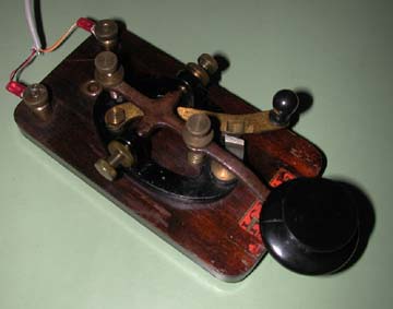
R-48 Telegraph Key / Made by Signal Electric Co.
Signal Electric Co. Model R-48 telegraph key. (Menominee, Michigan / circa 1919-1935). Brass construction, shorting lever ("dead man switch"), mounted on wood base with three rubberized feet. Directly under the key lever is a water-soluble decal (red field with black text) that reads, "Signal - Manufacturers of Electrical Products. Manufactured in L_____a by Signal Electric Mfg. Co. Menominee, Mich." This key appears to have the Navy style knob, which may not be original to the Model R-48 key.
Comparing this telegraph key to one in an old Signal Electric Co. catalog, it closely resembles the Signal Electric Co. Standard Key - Model R-48. List price when new was $3.65. The catalog description reads, "Well designed and correctly balanced for the operator who wants a good standard key at a moderate price. Very clean design, with polished key lever and lacquered fittings. Equipped with platinor contacts."
$20.00 / Horseheads, NY Winter Hamfest / February 25, 2006.
The history of the Signal manufacturing plant in Menominee, Michigan is detailed on web page referenced below, but the overview is that the plant was founded in 1892 producing various electrical products keeping step with changing technology. It remained open until 2005 when production was moved to Mexico.
References
Source: Menominee County Historical Society
Jim Callow (K8IR)
Menominee, Michigan
k8ir.com
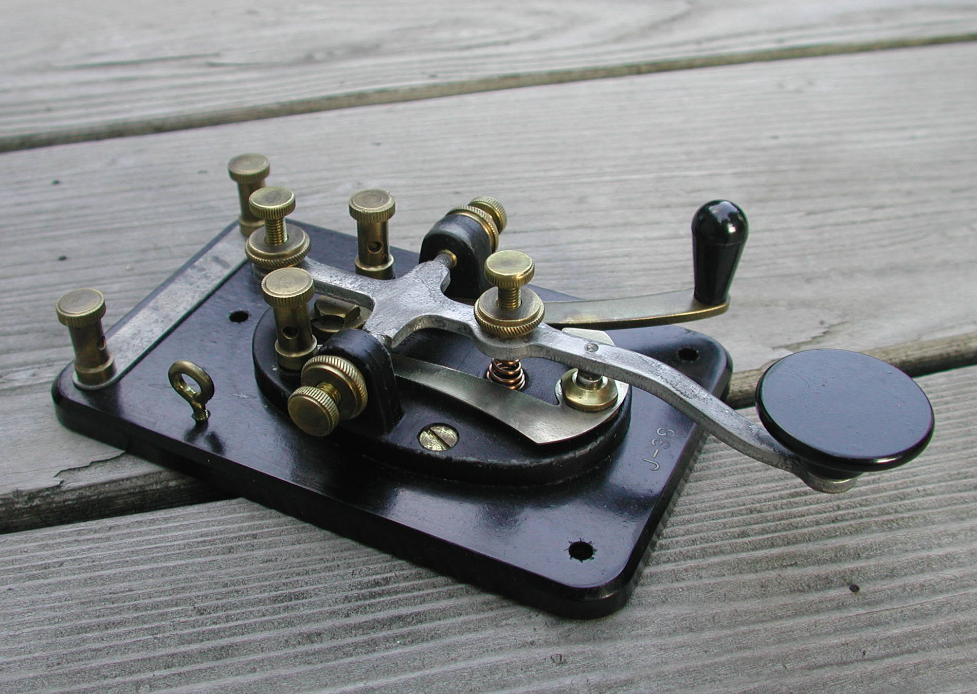
J-38 Telegraph Key / Made by Lionel
This WWII military J-38 key was made under government contract by the Lionel Corporation (the model train company). Purchased for $30 at the Antique Wireless Association (AWA) Conference on August 22, 2009. The vendor was Bob Fortman (WE2T). Photo: August 24, 2009.
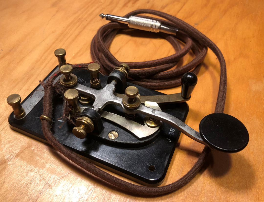
The same J-38 Telegraph Key
The J-38 telegraph (a.k.a. CW or Morse code) keys were made by various companies for use in WW II by the US Army Signal Corps. The Lionel logo is clearly stamped into the bottom of the base. The eyelet on the side is actually for a headphone lanyard. Updated photos: October 20, 2020.
For SSB work, with the Kenwood TS-530S, I use a 1948 style, Astatic (Conneaut, Ohio) microphone with a non-amplified "grip to talk" UG8 stand and a DN-HZ "bullet" head. I found it at the Dayton Hamvention on Friday May 18, 2007 and it was in excellent condition. The original cable had been replaced, but fortunately, the wire colors matched the diagram on the inside of the base. It needed a 4-pin microphone connector so that it would plug into the Kenwood TS-530S transceiver. Price for the microphone was $50.00 and the 4-pin connector was $1.00.For Reference Only (FRO): The Astatic DN-HZ head is similar in style to the Astatic 10-D microphone head. The 10-D is considered to be one of the best microphones ever made by Astatic.
Photo (left): Astatic microphone with a non-amplified "grip to talk" UG8 stand and a DN-HZ "bullet" (or "cucumber") head.
Photo (right): Schematics and description of how I adapted the Astatic microphone to the Kenwood TS-530S transceiver.
The cable on the Astatic microphone was a 4-conductor with a shield. Black and white (clear) wires ran inside the shield. The red and blue wire were not shielded. There was a schematic pasted to inside of the base of the Astatic microphone. The Kenwood Operator's Manual also included a schematic and verbiage on the microphone circuit with respect to operating with the VOX.
The final 4-pin microphone connector pin-out was:
Pin 1 = white wire (goes to the microphone circuit). See Note 1, below.
Pin 2 = red wire (P.T.T. switch - normally open).
Pin 3 = blue wire (P.T.T. switch - normally closed).
Pin 4 = shield.On Friday June 1, 2007 at the Rochester Hamfest, I bought a proper black microphone cable. It was brand new, and came with the 4-pin connector already soldered to the end. However, the wire colors were soldered to the "wrong" pins (if the diagram on the inside of the microphone base was to match the actual pin-out). The cable had one extra conductor (yellow). The other wire colors were the same as noted above, with the exception that the only shielded wire was the white conductor. This was fine, as the Astatic schematic showed the white wire in the shield (along with the black wire). Since the black wire was not used, it did not matter if it was shielded on the new cable or not. So, after replacing the cable, and re-soldering the pins of the connector, the wire colors on the schematic diagram still matched the actual cable colors. Cost of the microphone cable was $5.00.
- Per the Kenwood TS-530S Operator's Manual, the microphone needs to have the microphone circuit isolated from the P.T.T. circuit so the VOX feature will work. I determined that I had to disconnect (unsolder) the internal white wire at terminal #8 on the inside base of the microphone so as to isolate the microphone circuit from the P.T.T. circuit.
- Black wire was not used.
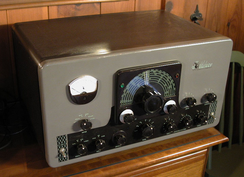
E.F. Johnson "Viking Valiant" Transmitter
View the Viking Valiant Restoration Page
Specification Overview
Modes: AM/CW
Bands: 160 - 10 Meters
Input Power: 200 watts AM / 275 watts CW02-nov-2007 (Friday): Attended the annual Rochester Amateur Radio Association (RARA) auction, and bid on this E.F. Johnson Viking Valiant AM transmitter. A "TR switch" (a.k.a. Dow Key Relay) is used to toggle the antenna between the transmitter and the Hallicrafters S-40 receiver. I was considering a Johnson "Viking Ranger", but others who knew heavy, old tube radios (a.k.a. "boat anchors") convinved me the extra power of the Valiant would be useful.
Local radio historian, raconteur, Antique Wireless Association (AWA) Museum curator, and RARA auctioneer, Ed Gable (K2MP) had this to say about the history of this particular Valiant..."The set was purchased by the County of Monroe (NY) for RACES in the mid 1960s. The Radio Officer was Chuck Brelsford (K2WW). The Valiant was used as the Net Control Station (NCS) station on the NY Counties 75 meter Civil Defense (CD) Net. It was first used in the radio room in the basement of the County Hospital at the corner of Westfall Road and East Henrietta Road."
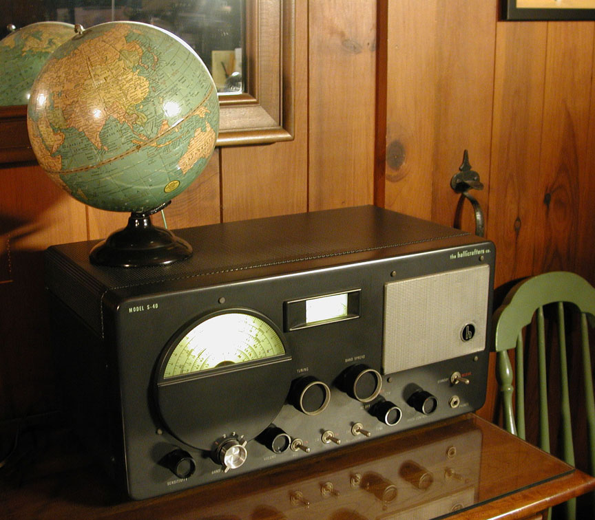
1946 Hallicrafters S-40 Receiver
View the Hallicrafters S-40 Restoration Page
Tuning Range
Band 1 (broadcast): 550 - 1700 kHz
Band 2 (short-wave): 1.68 - 5.4 MHz
Band 3 (short-wave): 5.3 - 15.8 MHz
Band 4 (short-wave): 15.3 - 44 MHzThe Hallicrafters S-40 receiver is used with the Viking Valiant transmitter. The antenna is toggled between the transmitter and receiver by way of a "TR switch" (a.k.a. Dow Key Relay). To complete the AM station, I use an Astatic D-104 microphone, and a Johnson Viking Matchbox (250-23-3) antenna tuner.
Incidentally, the 8" Terrestrial Globe on top of the Hallicrafters "S-40" was manufactured by the Geo. F. Cram Company of Indianapolis, Indiana. It is a Model "80", and includes the country of Italian East Africa, which only existed from 1936-1941. It also includes short wave radio stations around the globe and their call signs. The symbol for the short wave stations is a red antenna tower.
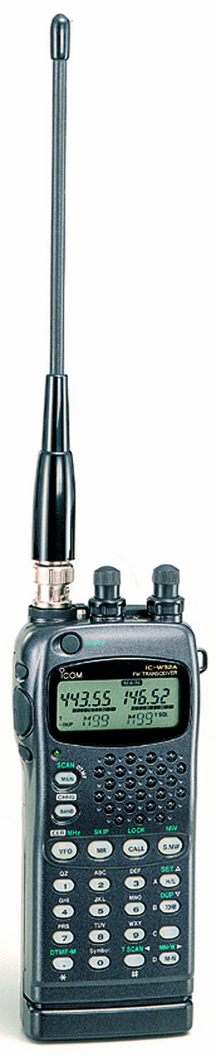
Purchased the ICOM IC-W32A from Universal Radio on November 28, 2005. Photo uploaded September 29, 2015.
Reference Material
- ICOM IC-W32A Owner's Manual
- ICOM IC-W32A Service Manual
- ICOM IC-W32A Product Specs: www.universal-radio.com/catalog/ht/0838.html
Standard Features
- Flexible BNC antenna "stub"
- Belt clip (metal)
- Wrist strap
- BP-173 Battery pack (NiCad Battery Pack 9.6V 600 mAh)
- BC-110A Battery wall charger. Charger plugs fits into the radio receptacle (3.4 mm O.D x 1.3 mm I.D.). See Radio Shack part numbers, below.
Auxiliary Power
- Battery charger and Aux. power cord receptacle on the ICOM IC-W32A radio:
- Radio Shack / Adaptaplug "H" (p/n: 273-1711 / 3.4 mm O.D x 1.3 mm I.D.)
- Radio Shack Adaptaplug Socket (p/n: 273-1743)
Options
- ICOM LC-128 / Vinyl carrying case
- ICOM BP-170 / Battery case (takes 4 AA cells)
- ICOM CP-12L / Cigarette lighter cable with noise filter
- ICOM HM-46 / Compact speaker microphone
- Diamond RH77CA HT antenna. 16", BNC, ¼ wave (2 m), ½ wave (70 cm)
- Mobile magmount antenna for the ICOM "IC-W32A" HT
- ARRL Repeater Directory (2005/2006 edition). Covers 420-450 MHz and 144-148 MHz
Background
When accessing the K2RRA 146.88 repeater, I was getting an automated message stating, "Your PL tone should be 110.9, but is actually 88.5." I had correctly set my Repeater Tone (RT) ("T" in the ICOM IC-W32A display) (encode tone) to 110.9. However; the CT (Tone Squelch - decode tone) was still set to the default setting of 88.5. It was this tone (the CT - Tone Squelch - decode tone) that the automated repeater message was referring to. The solution was to set both tones (encode and decode) to the same frequency. It is not clear why ICOM allows the RT and CT tones (encode and decode) to be set to different frequencies, especially after reading the notes from the ICOM website, below.
Yaesu FT-7800R dual band (2m / 70cm) FM "mobile" Transceiver
Yaesu FT-7800R dual band (2 meter / 70 centimeter) FM
transceiver
Original photo: November 18, 2006 /
Enlarged photo (click the little one): September 30, 2015
Yaesu FT-7800R Output Power
2 meters: 5, 10, 20, 50 watts
70 centimeters: 5, 10, 20, 40 wattsFirst FT-7800: Universal Radio (via mail-order) / $259.95 / July 6, 2006
Second FT-7800: R&L Electronics (www.randl.com) (2008 Dayton Hamvention / Saturday May 17, 2008) / $228.95 (included the YSK7800 Separation Kit). The cloning kit (ADMS-2K) Windows software for the Yaesu FT-7800 was another $39.95.
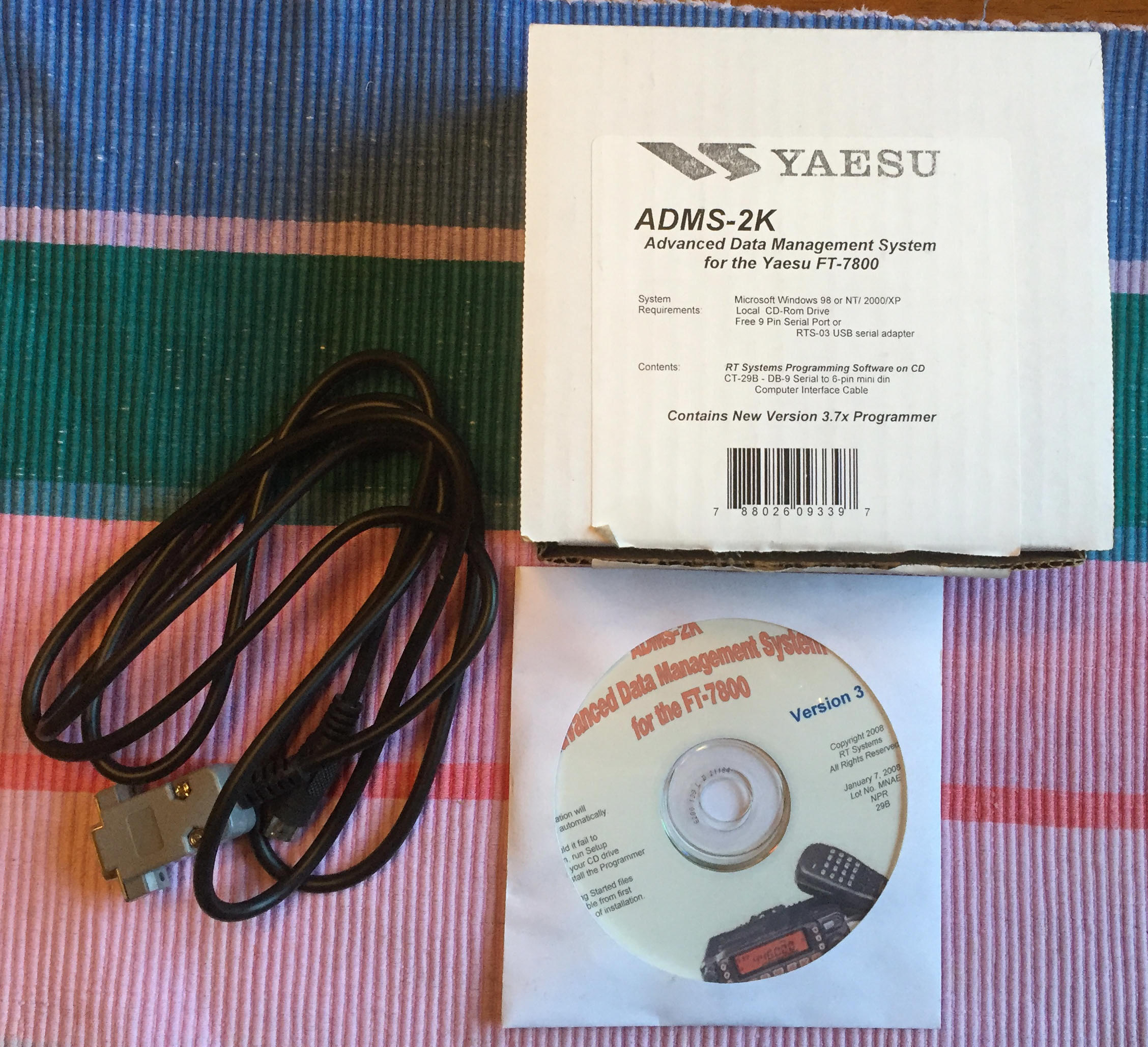
ADMS-2K cloning kit for Yaesu FT-7800 (photo: April 16, 2016 / iPhone 6)
The cloning cable (included with the ADMS-2K kit) is part number: CT-29B, which has a DB9 Serial connector on one end, and a 6-pin mini din on the other.
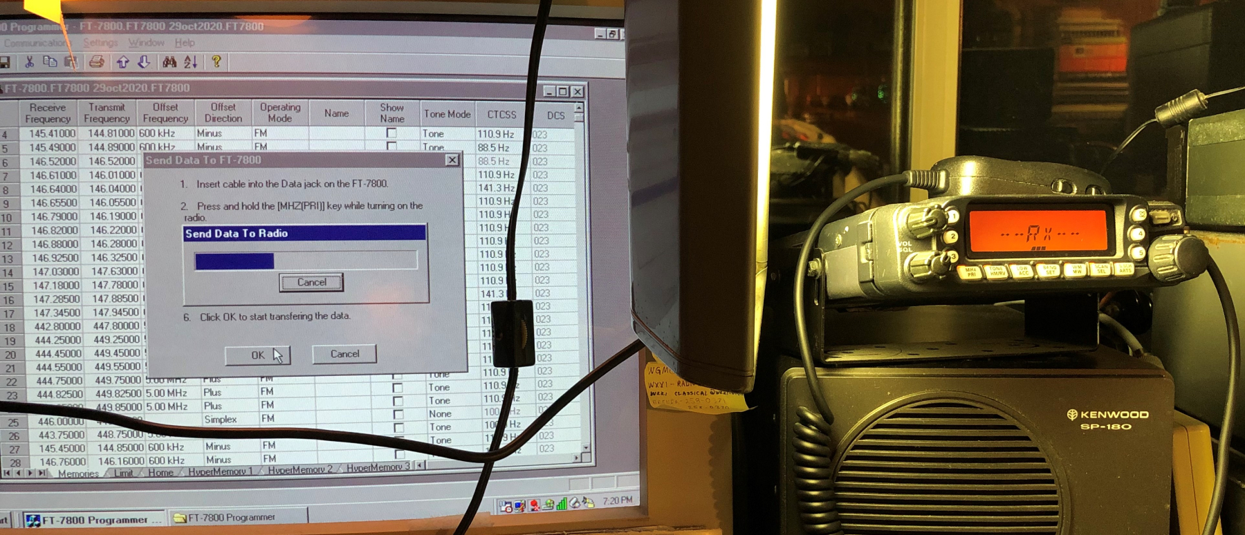
Since the cloning cable has a DB9 serial connector (male) at one end, either the Win98SE computer needs to remain available (for its serial port), or a USB-to-DB9 serial adapter for the Win10 laptop is needed. First verify the ADMS-2K software can be installed on Win10.
Yaesu FT-7800R Product Specs: www.universal-radio.com/catalog/fm_txvrs/3780.html
Yaesu FT-7800R Eham.com Reviews: www.eham.net/reviews/detail/3685
Yaesu FT-7800R Operating Manual: radio_Yaesu_FT-7800R.pdf
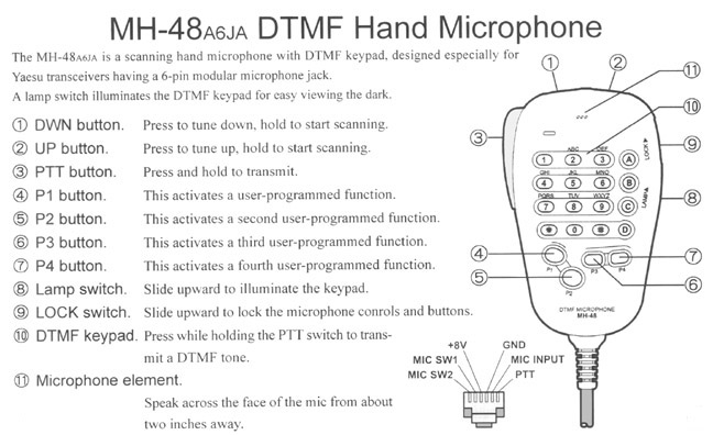
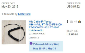
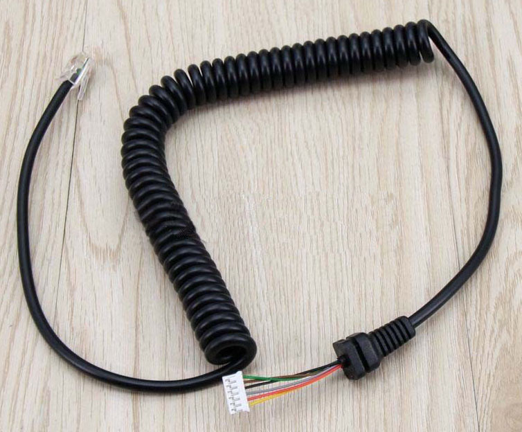
Original Yaesu MH-48 DTMF hand microphone, and subsequent cable/cord replacement
Update May 23, 2019 (Thursday):
The black cord/cable microphone sheath began to deteriorate near the base of the mic. Functionality was still 100% on both units, but decided to get proactive, and purchased two microphone cables on eBay – one for each Yaesu FT-7800. Each cost $7.96 = $15.92 total (shipping included). The new cords arrived May 28, 2019 and they were installed and verified on the air.Notes:
- Original (as sold) Yaesu FT-7800 microphone was № MH-48A6J.
- Universal Radio did not sell the cable as a separate part, but recommended contacting Yaesu parts, and provided their phone number.
- Yaesu parts (Tel. 714-827-7600) wanted $27.30 per cable (Yaesu № T9206534).
Eliminate (mute) the Toronto 145.11 Repeater (VE3WOO) when Listening to the Bristol 145.11 Repeater (WR2AHL)
Using "Split" (separate) Encode (ENC) and Decode (DEC) Subaudible Tones with the Yaesu FT-7800RUnfortunately, the Yaesu FT-7800R does not permit configuration of "split" (separate, different) CTCSS tones for ENC and DEC for a given repeater frequency. So, it is impossible to mute the Toronto repeater at this time using the Yaesu FT-7800R. Note that the newer, Yaesu FT-7900R is capable of split ENC/DEC operation.
Scenario 1: If the local repeater ENC tone is 110.9 (Hz), the only tone that can be used for DEC is 110.9. This precludes muting other repeaters on the same frequency – if and when the local repeater uses different (a.k.a. "split") tones for ENC and DEC.
Scenario 2: The 145.11 Bristol repeater (WR2AHL) uses 110.9 for ENC, and 88.5 (Hz) for DEC, so the Toronto repeater (VE3WOO) cannot be muted (when the conditions are right for the Toronto system to reach down into the Finger Lakes region of New York state).
Note: The Operating Manual has "Split Tone Operation" (p. 31), which seemed promising, but it did not solve this problem.
N2AWA / September 22, 2014
July 13, 2006:
Here is my eham (www.eham.net) review of the Yaesu FT-7800R..."After sending my new ICOM 2720H back after six days (it would not stop transmitting on high and medium power with the control head mounted to the main unit with the optional MB-85 bracket), I took more time to read the reviews of the Yaesu FT-7800R because I plan to use the rig in the shack with the control head mounted directly on the main unit. I did not want to get burned again. The vendor refunded my money for the 2720H, but it was not something I wanted to repeat. The Yaesu FT-7800R comes standard with the radio connected to the main unit. The remote cable (YSK-7800 Separation Kit) is an option. I was concerned that the problem might be with something in the shack (antenna, coax, connectors, power supply, etc.) I verified all of those things with another radio before buying the FT-7800R. After owning the Yaesu FT-7800R for a few days, I can say the following things (some are in response to other comments made in the eham.net forum). The display can be adjusted to a comfortable level for use in the shack. The display is also much nicer in life than in any of the online photos I saw. True, the view angle of the LCD is critical, but that is not unique to this rig. The default brightness of the display is a bit high for the shack, but again, adjust it down, and it’s fine. I also like the illuminated buttons on the rig. They are easy to see, especially in low light situations. The microphone buttons can also be illuminated via a switch on the side of the mic. I have been able to reach repeaters (both VHF and UHF) that I was not able to reach with the ICOM 2720H and an ICOM 2100H (on loan for the 2006 "Tour de Cure" from Tim WB2PAY) and my ICOM IC-W32A (the W32A “HT” may not be a fair comparison here). It sounds like I’m bashing ICOM, but that is not the intent. There was one UHF repeater in particular that I have been trying to get into from my home QTH. It is located in a metro area, and my QTH is 30 miles away, in a rural area. The FT-7800R reaches it with no problems, full quieting. I was beginning to suspect my antenna as the reason I could not reach the repeater before, but this shows that you need the right radio to do the job. Maybe it’s the extra 5-10 watts on UHF that the other rigs did not have. With the FT-7800R, the maximum power on UHF is 40W. Audio reports have all been favorable so far. Only strange thing is that the microphone cord plugs into the right side of the control head. It would be more ergonomic if it snapped into the left side. Quite pleased with the ease of programming so far, but I have not played with the labeling of repeaters or putting repeaters in various banks. The manual is easy to understand. Once you get into the rhythm of programming the frequencies, it's only a couple of button presses to program the next sequential memory slot. Regarding sensitivity, I had previously programmed many repeaters into my ICOM IC-W32A HT (my only VHF/UHF rig up until now) that seemed to be dead most of the time. I programmed the same repeaters into the Yaesu FT-7800R and am now hearing traffic where I thought there was none. To respond to the comments about the "lightness" of the detents of the tuning dial – they are a bit on the light side, but not a problem for me. Finally, overall improvements would be to have the microphone cord come out the left side of the control head, provide some display color options, and to make the tuning dial a bit heavier to click through the detents. Otherwise, Nice job Yaesu!"
Technical Problem with the Yaesu FT-7800R / Power Button Broken October 26, 2014:
http://www.yaesu.com/?cmd=ContactUs
Wrote to Yaesu about a technical problem with the FT-7800RThe FT-7800R (Studio L / Ser. Nr. 7N750982) turned off unexpectedly (26-oct-2014) while monitoring a repeater. It was running off a 12 volt lead acid, 31 Ah cell, and the voltage measured normal (about 12.4 v). The power switch seemed to have a delay. When pushed, the rig came on (or went off) a few seconds later. Once it was turned off, it kept coming back on (by itself) about 10 seconds after being turned off. I bought this rig new in May 2008, and it had never done this before.
27-oct-2014:
The in-line fuse was fine. The battery voltage measured 12.4 volts. Tried the rig on a 12 volt AC mains power supply, but it exhibited the same behavior. The radio uses surface mount technology (SMT), which is beyond the scope of what I can work on, so boxed it up, and sent to Yaesu tech. support in California. Freight (USPS): $25.40 with insurance for $330.04-nov-2014:
Yaesu called to say the repair would be $50.42 plus shipping to "replace two pots." The rig should be repaired and shipped by the end of the week (Friday November 7, 2014).11-nov-2014:
Received radio from Yaesu (via Fed-Ex) but the problem was not fixed. It began to shut on and off by itself.
Total: $25.40 (my freight) + $50.42 (repair) + $14.00 (their freight) = $89.8212-nov-2014:
Spoke to Yaesu again and described the problem in more detail. The unit has to be connected to power, but powered off. Then the technician needs to wait for it to turn on automatically. This can take anywhere from a few minutes up to an hour. Once this happens, it begins turning on and off by itself, and the power button will no longer work. They will cover my postage, and the previous repair has a 90 day warranty, so they will try to make it as easy as possible. Sent the unit back to Yaesu. Freight (USPS): $21.00 with insurance for $300.17-nov-2014:
USPS tracking confirmed radio arrived at Yaesu in California.21-nov-2014:
Yaesu confirmed the radio arrived and was assigned to a technician.05-dec-2014:
Yaesu confirmed the technician was able to duplicate the problem in the lab (finally!). Allegedly, they found and repaired cold solder joints. Radio was returned free of charge. Received it from FexEX 09-dec-2014. Waiting to see how Yaesu handles covering my shipping costs ($21) as previously agreed.
Update July 23, 2017: (Sunday)
The old 12 volt, 31 Ah lead acid battery finally bit the dust. It would no longer hold a charge. Replaced it with a new Duracell Ultra (SLAA12-35C) 12 volt, 33 Ah lead acid battery from Batteries Plus at 1100 Jefferson Road. It had a one year warranty. Cost: $89.99 + $7.20 tax = $97.19.
ICOM IC-260A VHF (2 meter) FM/SSB/CW Transceiver
This radio was part of Russ Schroeder's estate (W2DYY/SK) and came to my shack on July 4, 2008 by way of Lynn (W2BSN). We knew Russ through the Antique Wireless Association (AWA).
I skimmed through the operating manual (photo copy) and began using the rig on July 7, 2008 to check into the Rochester VHF Group Net (held Monday nights at 9:00 p.m. on 144.260 MHz). Photo of IC-260A taken Saturday July 26, 2008.
Using the ICOM IC-260A in high power mode (10 watts) with the Comet GP6 vertical antenna (6.5 dB gain on 2 meters) the rig has an equivalent output power of 44.668 watts (10 watts output to the antenna, 6.5 dB antenna gain = 44.668 watts). Recall that 3 dB gain yields about 2x the input power.
The ICOM IC-260A has two possible memory channels, but needs the optional "wall-wart" power supply to save them. Otherwise, the memory is lost when the main power is removed. The Molex style power connector at the back of the rig has three pins. Two are for plus and minus 12 volts and the third pin is for the optional wall wart power supply. One wire from the wall wart goes to the third Molex connector pin and the other wall wart wire would go to ground.There is no way to enter the frequency digitally with the ICOM IC-260A. The operator needed to spin the tuning dial to get where they were going. This was how it was done back in the good old days. There was an optional snap-on tuning dial accessory to make the spinning less tedious, and fortunately, this radio had one (see photo).
The S-meter lamp was not working when I got the radio. I took it apart (Saturday July 12, 2008) and discovered the miniature "grain-of-wheat" bulb was located inside the S-meter assembly. I replaced it with an identical 12 volt, 60 mA "grain of wheat" micro lamp (available at Radio Shack [Model: 272-1092 / Catalog # 272-1092]) on Saturday July 26, 2008.
The microphone that came with this particular IC-260A was the "IC-HM8." I do not think this was the original microphone.
- Frequency Range: 144-148 MHz (5 / 1 / 0.1 kHz steps)
- Modes: FM / SSB / CW
- RF Power Output: High: 10 watts / Low: 1 watt
- Manufactured: 1979 - 19xx
ICOM IC-260A Product Specs: www.rigpix.com/icom/ic260a.htm
ICOM IC-260A Eham.com Reviews: www.eham.net/reviews/detail/923
ICOM IC-260A Operating Manual: www.obairlann.net/reaper/ham/ic-260/manual
ICOM IC-260A Photos: www.muppetlabs.com/~reaper/ham/ic-260
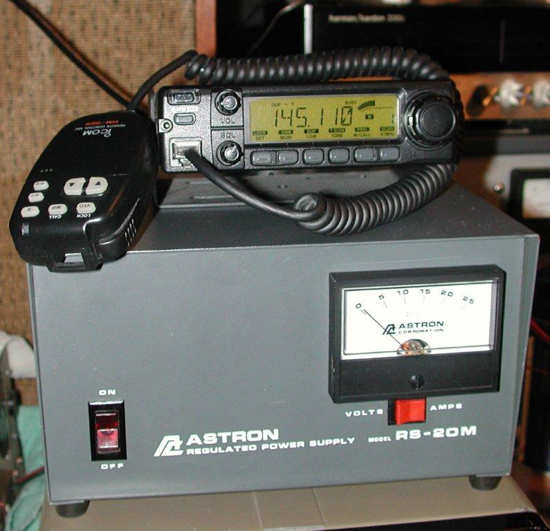
ICOM "IC-2100H" VHF (2 meter) FM Transceiver
with Astron "RS-20M" 20 Amp (16 Amp continuous) Linear Power Supply
- ICOM IC-2100H Operating Manual
- ICOM IC-2100H Addendum (HM-133S microphone supersedes HM-98S)
- ICOM IC-2100H Specifications (courtesy Universal Radio)
Purchased the ICOM "IC-2100H" VHF (2 meter FM mobile) transceiver June 4, 2011 at the Rochester Hamfest. The vendor was Jerry (KB2QIU). Price was $80 including the operating manual, "HM-98S" microphone, mounting bracket, and power cords. It belonged to his mother who passed away about a year earlier. I erased the existing memories and programmed my preferred repeaters in about an hour. The equivalent replacement ("IC-2200H" 2 meter FM mobile) costs about $170 plus shipping or tax. Used examples of the 2100H in good condition were going for $125 (or more) through online auction sites.
The other Rochester Hamfest acquisition was the Astron "RS-20M" (20 Amp; 16 Amp continuous) regulated linear power supply (with single Volt/Amp meter) as shown in the photo. It set me back $65 (still available new for $125 - $145). The vendor was Joe (NW2A). The ICOM IC-2100H and Astron power supply worked well together with a flexible J-pole antenna; easily hitting all local repeaters from the basement-level N2AWA electronic shop.
27-oct-2014:
The IC-2100H was taken from the basement workshop and pressed into service (in Studio L / Living Room) when one of the Yaesu FT-7800R rigs was sent back to Yaesu for service.IC-2100H "Quick and Dirty" Operating/Programming Notes (Look ma, I'm not using the manual!)
- The ICOM IC-2100H is a 2-meter only FM rig (no 70 cm / 440 mode).
- Monitor Repeater Input Frequency: Press [MONI]
- Change Output Power Level: Press [DUP/LOW]. Two levels display - LOW, MID, and for HIGH, nothing displays.
- Simplex Mode: Push and hold [DUP/LOW] button to select a duplex setting. There are three duplex settings available: minus duplex (“DUP–” appears), plus duplex (“DUP” appears) and simplex (no indicator appears).
- Turn OFF (disable) Subaudible Tone Encoder (for simplex): Push [TONE] one or more times until no tone indicators appear.
- Save Changes to Memory: Press and hold [S.MW MW] (beneath power button).
Eliminate (mute) the Toronto 145.11 Repeater (VE3WOO) when Listening to the Bristol 145.11 Repeater (WR2AHL)
Using "Split" (separate) Encode (ENC) and Decode (DEC) Subaudible Tones with the ICOM IC-2100HUnfortunately, the ICOM IC-2100H does not permit configuration of "split" (separate, different) CTCSS tones for ENC and DEC for a given repeater frequency. So, it is impossible to mute the Toronto repeater at this time using the ICOM IC-2100H.
Scenario 1: If the local repeater ENC tone is 110.9 (Hz), the only tone that can be used for DEC is 110.9. This precludes muting other repeaters on the same frequency – if and when the local repeater uses different (a.k.a. "split") tones for ENC and DEC.
Scenario 2: The 145.11 Bristol repeater (WR2AHL) uses 110.9 for ENC, and 88.5 (Hz) for DEC, so the Toronto repeater (VE3WOO) cannot be muted (when the conditions are right for the Toronto system to reach down into the Finger Lakes region of New York state).
Note: ICOM IC-2100H Operating Manual outlines a feature called Tone Squelch, which seemed promising, but when the Tone Squelch value was set to 88.5, and the ENC tone value was set to 110.9, I could not get into the Bristol repeater. When the Tone Squelch value was set to the same value as "T" (ENC tone), i.e. 110.9, I could access the repeater fine.
N2AWA / October 28, 2014
Tim (WB2PAY) verified the same results on his IC-2100H / October 29, 2014
Magmount (version 1)
For mobile use (with my ICOM "IC-W32A" HT), I originally bought a Valor ProAm MM-270B antenna. The Valor ProAm MM-270B was a miniature magnetic mount, dual band antenna for 2 meters and 70 cm. It could be used to transmit on 140-148 and 440-450 MHz, and was capable of handling 25 watts. This stainless steel antenna was only 20 inches tall, and came with nine feet of RG-174 coax, terminating to a male BNC plug. This inconspicuous antenna used an ABS rare earth magnetic base with a 1 1/8 inch diameter base and weighed only two ounces. Unity gain (1:1, i.e. no gain characteristics). Typical VSWR is 1.5:1. $18.95 + $4.95 shipping. Universal Radio (universal-radio.com). Ordered 16-dec-2005. Arrived on 30-dec-2005. Two weeks to come from Ohio?!Magmount (version 2)
Update 30-sep-2008: The Valor ProAm MM-270B magmount antenna finally ceased to function due to a worn coax connection at the point where it entered the magnetic base. So, I began using a BNC-to-SO-239 adapter with my Comet "M-24M" magmount antenna (Dayton Hamvention 2008). The Comet M-24M was larger (uses RG-58 coax) and the magnet footprint was larger.External, 5/8 wave, vertical antenna for the Yaesu FT-7800R VHF/UHF rig (Studio "A" / Main Shack)
Dayton Hamvention / May 19, 2007 / VIS Amateur Supply / Coffeeville, Alabama.
Comet GP6 VHF/UHF antenna / $141.00 plus tax = $150.87
The Comet GP6 dual band, dual-section, fiberglass vertical base antenna is for 2 meters (5/8 wave x2) and 70 centimeters (5/8 wave x5). It mounts on a 1.5" to 2.25" diameter mast (not supplied).Comet GP6 Specifications
Frequency: 2 meter / 70 centimeter
Gain: 6.5 dB (2 meters) / 9.0 dB (70 centimeters)
Power: 200 watts
VSWR: 1.5:1 or less
Connector: SO-239
Height: 10.3 feet
Weight: 4 poundsJ-Pole antenna for the Yaesu "FT-7800R" VHF/UHF rig (Studio "L" / Living Room)
Flexible J-Pole. Male BNC connector (screw-on type BNC connector) to 20' of RG-58U coaxial feed line to a "dual band" (2 m and 70 cm) 300 Ω twin lead J-pole antenna. The 300 Ω twin lead is encased in a three foot section of PVC pipe, which was originally suspended from the gutter sill at the home QTH, and later hung inside from a north-facing window. 27-jun-2006: SWR measured 1.2:1 at 145.11 MHz. There is a 90° BNC to PL-259 adapter at the back of the Yaesu FT-7800R radio. See Antenna References for flexible J-Pole purchase information.Flexible J-Pole antenna for the ICOM "IC-2100H" VHF/UHF rig (Studio "B" / Basement)
Male BNC connector (screw-on type BNC connector) to 20 feet of RG-58U coaxial feed line to a "dual band" (2 m and 70 cm) 300 Ω twin lead J-pole antenna. 27-jun-2006: SWR measured 1.2:1 at 145.11 MHz. See Antenna References for flexible J-Pole purchase information.Flexible (VHF / UHF) J-Pole for the "ICOM IC-W32A" HT (Studio "G" / Go Bag)
This antenna is kept in the "go bag" and uses the thin RG-174/U coax (I call it spaghetti coax) with 300 ohm TV twin lead cut to the J-Pole configuration. Just toss it over a tree branch, or a curtain rod, and you're transmitting and receiving!RG8 Coaxial Cable
The Wireman thewireman.com
Mfr./brand: CQ 4XL (CQ "Super 8") / Wireman p/n: 106
30' @ $0.94/foot = $28.20
Two (2) PL-259 Amphenol connectors ~$2.80 each.
The coax will be used with the Comet GP6.Wireman's description of the "CQ Super 8" coax:
"Born in 1991 as an experimental coax, similar to Flexi-4XL, but with a foam dielectric instead of the air, or semi-solid polyethylene, dielectric. Very similar to the recent Belden 9913F7 and Times LMR 400UF, but now with a great new, tougher, higher temperature, UV resistant jacket and greater flexibility. With its longer track record, and lower price, "Super 8" continues to improve as the technology is perfected, and indeed, the current production has almost the same loss characteristics as the expensive items."Assembled and erected the Comet GP6 antenna on Saturday, June 9, 2007. Used four 1/4" x 4" lag bolts to secure the hardware kit (provided) to the eave of the house. Ran the 30' of RG8 coaxial cable along the inside of the eave, and down into the shack. Under the eave, the coax is supported with large cup hooks. The antenna made a big difference as to the repeaters that I could reach.
Grounding
Purchased the following from The Wireman (www.thewireman.com) during the 2007 Dayton Hamvention.
- Knife switch DPDT ($4.95)
- Grounding buss: CQ "GD6" 6 SO-239 connectors mounted on L shaped stock, with ground screw connector ($24.95)
Describe radio station grounding techniques here: (forthcoming...eventually, maybe, someday).
Battery Packs (misc. notes) for VHF/UHF "HT" (Hand-held / a.k.a. "Handie Talkie") transceivers:
Pros of NiCad: charges quickly.
Cons of NiCad: develops charging "memory" (suspected not proven).
Pros of NiMH: Higher capacity than NiCad
Cons of NiMH: Reduced performance at high discharge rates
Pay attention to the mAh rating for the battery packs such as:
NiCad Battery Pack 9.6V 600 mAh
Google "amateur radio NiCad versus NiMH battery" for more information.
Paraphrase from the ARRL Handbook, 2005 edition, pp 17.21.:
NiMH has a higher capacity (twice) than NiCd and freedom from memory effects. A barely noticeable downside is the reduced performance at very high discharge rates. The longer run time and higher capacity far outweighs this. Self discharge may be higher than NiCd but again not noticeable. If you need very high peak currents then the NiCd is better, but in the HT it is better to use the NiMH.12-apr-2006:
Purchased 8 rechargeable NiMH AA batteries for the ICOM IC-W32A. These will work in the ICOM BP-170 battery case (takes 4 AA cells)
Rechargeable NiMH AA batteries / Set of 4 / Duracell / 2500 mAh / $12.99
Rechargeable NiMH AA batteries / Set of 4 / Duracell / 2500 mAh / $12.99
Duracell "QuickCharger" / for NiMH or NiCd / AA or AAA / $9.99
Rite Aide Pharmacy 2918 Dewey Avenue Rochester, NY.Purchase Dates Unknown:
Rechargeable NiMH AA batteries / Set of 4 / Duracell / 2650 mAh / $9.38 at amazon.com as of October 4, 2011
Rechargeable NiMH AA batteries / Set of 4 / Duracell / 2650 mAh / $9.38 at amazon.com as of October 4, 201120-oct-2014:
Rechargeable NiMH AA batteries / Set of 4 / Powerex (Japan) / 2700 mAh / $15.99 at Batteries Plus Bulbs #820 / 1100 Jefferson Rd.For Reference Only / Universal Battery Charger:
Maha MH-C777PLUS-II Universal LCD Charger / Analyzer / Conditioner
$69.95 via universal-radio...
www.universal-radio.com/catalog/hamacc/1392.html
Clubs / Vendors / Forums / Nets
Amateur Electronic Supply (AESHAM.com)
www.aesham.com
Amateur Radio Association of the Southern Tier (Elmira, Horseheads)
www.arast.org
Hamfests in "Summer" (last Saturday in September) and Winter (February)American Radio Emergency Service (ARES)
www.monroecountyemcomm.org
American Radio Relay League (ARRL)
www.arrl.org
On September 18, 2006 my XYL and I visited the ARRL headquarters in Newington, Connecticut. If you ever get the chance to visit, I highly recommend it. The facility offers hourly tours, and the staff was friendly. They also have a store where you can purchase any of the ARRL publications, and other goodies offered online. The W1AW station is also available for tours, and operation, as long as you bring a copy of your current amateur radio license.Breakfast Club
hamdata.com
Founded January 1, 1958. A friendly Net on 3.973 MHz for those HAMs who rise early. Commences at 0500 (eastern USA time). Ten check-ins qualify you for membership. For $7.00 per annum, they send a 10 page, color newsletter.Drumlins ARC (Newark, NY)
Hamfest
drumlinsarc.org/hamfest.htmEham.net (Reviews, forums, etc.)
www.eham.net
F.C.C. Universal Licensing System
wireless.fcc.gov/uls
Geratol Net
geratol.netKenwood TS-530S Discussion Forum
groups.yahoo.com/group/TS-520_820_530_830
Lehigh Valley Amateur Radio Club
www.w3oi.orgMark S. Miller (AK3M)Morse Code (CW) References
ARRL Element 2 (Technician Class) exam held Friday September 16, 2005 (7:00 p.m.) with Lehigh Valley Amateur Radio Club (LVARC) in Allentown, PA at Red Cross building near the Lehigh Valley International Airport at 2100 Avenue A.
Ray Goff (G4FON) Koch CW trainer
www.g4fon.co.ukMorse Code test page
www.aa9pw.com/radio/morse.htmlMorse Code Programs
www.ac6v.com/morseprograms.htmMorse Academy
Use search engine. URL was not up last time I checked (07-mar-2008).RufzXP
www.rufzxp.net
"Rufz" is the abbreviation of the German word "Rufzeichen-Hören", which means "Listening to Call signs."QRZ.com
Practice amateur license tests, discussion forum, etc.
www.qrz.comRadio QTH
Resources for "mining" amateur radio call sign data. Call sign weight, etc.
www.radioqth.netRochester Amateur Radio Association (RARA)
www.rochesterham.orgRARA Board of Directors
RARA General (Yahoo! Group)
On May 2, 2008 at the monthly RARA meeting, I was voted into the RARA Board of Directors. The term was one year. We met monthly at the Rochester Institute of Technology (R.I.T.) campus. At the first Board meeting, I was named "Chairman of the Marketing Committee." In this capacity, I organized various "regalia" items for sale with the RARA club logo, and was also responsible for ordering pizza for the Board meetings! Re-elected to the Board in 2009. Pizza was voted "out" in 2009, but chicken wings (after the meetings) were definitely "in."
groups.yahoo.com/group/rara-general
General Class Theory (ARRL Element 3) offered through RARA. The class began September 19, 2005 and I took the exam November 19, 2005, along with ARRL Element 1 (Morse Code 5 wpm). Got a perfect score on both exams. There was only one other student in the class.Ed Martin (K2QP) (ARRL Element 3 instructor)
Bob Marciano (KB2DVZ) (ARRL Element 3 student)Rochester DX Association (RDXA)
www.rdxa.com
Members-only majordomo email: mailman.qth.net/mailman/listinfo/rdxa
SIARC - Squaw Island Amateur Radio Club (K2BWK)
www.siarc.us
Straight Key Century Club
www.skccgroup.com
Universal Radio
www.universal-radio.com
Universal Radio is where I got the ICOM "W32A" (HT) and mag. mount antenna (Valor ProAm MM-270B) for the vehicle. Also got the Yaesu FT-7800 "mobile" dual band rig at Universal.
QSL cards (generic) www.universal-radio.com/catalog/hamacc/1116.html
$4.95 / 100 / ordered: 10-apr-2006 / received: 14-apr-2006.Log book (generic) www.universal-radio.com/catalog/books/2845.html
$3.95 / 30 pages / ordered: 10-apr-2006 / received: 14-apr-2006.

My QSL card measures 6" x 4.25" – the maximum postcard size for basic postal rate ($0.26) as of this writing (January 2008). It is slightly larger than the standard QSL card size of 5.5" x 3.5." The larger card enabled me to use a 1:1 copy of the original design. The postage stamps were acquired in Bracebridge, Ontario, Canada on July 26, 2005. I began designing the card in April 2006 and thought the stamps would make it look interesting. I affixed the stamps to a piece of construction paper and scanned the results into the computer. I used Adobe Photoshop (v. 6) to place my call sign on the front, and arrange the text on the reverse side.
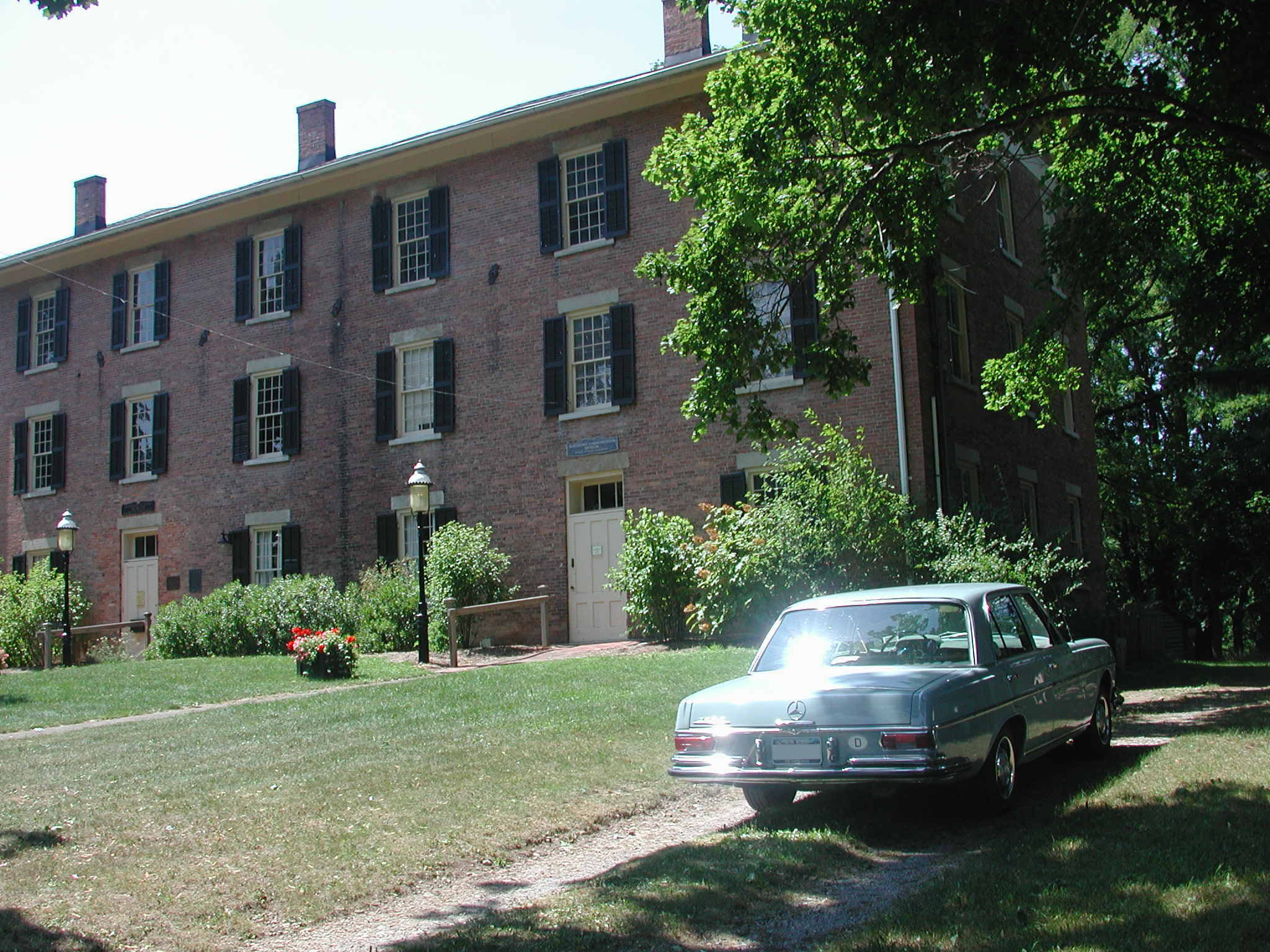
Other QSL card concepts – yet to be printed. The N2AWA call sign with the former AWA Museum (8 South Avenue / East Bloomfield / 14443) in the background. I took the photo August 11, 2007 with my 1966 Mercedes-Benz 250S sedan in the driveway – the first day I volunteered as a guide at the Museum.
Another QSL card design concept with the Olney vicarage as a cozy backdrop – looking similar to the former AWA Museum.
Essential QSL Card Data
The following information is required for a valid QSL
- Your call sign
- Other station's call sign
- Day
- Month
- Year
- Time (UTC)
- Frequency
- R S T
- Mode (CW, FM, USB, LSB, RTTY, PSK31, etc.)
Optional QSL Card Data
Believe it or not, the following information is considered optional
- Your name
- Address
- County
- Grid square
- Telephone number
- Email address
- Rig
- Antenna
- Check-boxes for: QSL (PSE / TNK)
- Comments or remarks, etc.
QSL Card Design
Typically, QSL cards are 5.5" x 3.5", but can be any size, and on almost anything (even a rock) as long as the "essential data" (see above) is included, which confirms the contact. Leave space on the back for the other station's postal address. If one side of the card is dedicated to a single image, it will be unavailable for contact data.QSL Card References
Modern Postcard (postcard sizes, USPS regulations, etc.)
www.modernpostcard.comLZ1JZ QSL cards. Good quality reported by HAMs
www.lz1jz.comQSL Man (full size QSL card images front and back)
www.w4mpy.com/cardthum.htmStar Cards Inc.
Emporia, Kansas
www.star-cards.net
Phil Edwardson
scinfo ]at[ star-cards.net17-apr-2006: Ordered 1,000 (yes, one thousand!) custom QSL cards from Star Cards Inc. Their standard price for full color cards (6" x 4.25") was $299 (plus $11.50 shipping). Since I prepared the artwork and layout (front and back) myself, I paid the "re-order" price of $269 (plus $11.50 shipping). The 6" x 4.25" dimensions were slightly larger than the standard (5.5" x 3.5") QSL cards. Total: $280.50 ($0.28 per card). I received a .pdf proof before printing. The cards were printed and sent on 04-may-2006. I received them by the middle of the following week (11-may-2006).
Some fun with numbers: For 1,000 units, the cost of each QSL card worked out to be $0.28. The price of a US postcard stamp was then $0.24. Thus, each QSL card would cost a total of $0.52 to send within the USA. So, until the price of postcard stamps changed, 1,000 cards cost a total of $520 (to print and send). If I send one card per week, this supply will last about 20 years (average cost of $26/year). If the number of cards I send increases to three per week, the supply will last about six years (average cost of $86/year). If the QSL card is sent to an international destination, I may need to include an IRC (International Reply Coupon) so that the cost of return postage is covered for the remote station. Most likely, I will use the Incoming and Outgoing Bureau services as a more economical means of QSL-ing to international destinations. For more detail on the Bureau services, see below.
27-dec-2007: Ordered 250 new QSL cards (from Star Cards) with the N2AWA call sign. Price was $72.80 plus $8.60 freight, so the total charge was $81.40. The cards arrived January 7, 2008. Again, Phil Edwardson was courteous and professional, and I recommend Star Cards to "all my friends out there in QSL land."
QSL Bureau Services
Executive Summary of DX QSL Bureau ServicesARRL:
Outgoing Service (for all USA zones): Search the arrl.org website
Incoming Service (select QTH zone): Search the arrl.org websiteIncoming Service / Zone 2:
NJDXA (North Jersey DX Association)
www.njdxa.orgInternational Postage
International Reply Coupons (IRC)
www.n6hb.org/s-a/irc.htmUniversal Postal Union (UPU)
www.upu.int/members/en/members.html
13-dec-2008:
Installed Echolink (2.0.908) on my Windows 98/SE home computer. The application worked well with a dial-up connection.
Update: June 2009:
Echolink also worked well with Windows Vista and a Digital Subscriber Line (DSL) after the DSL modem was configured to allow remote connections.Echolink (designed by Jonathan Taylor K1RFD) allows radio amateurs to connect to each another via Voice over IP (VoIP) either directly with their computers or to other nodes (radio repeaters) that are running the software. In Single User mode, all you need is a Technician Class amateur radio license and a computer with speakers, microphone and a dial-up internet connection. A radio is not needed to talk to other HAMs around the world with Echolink! By using the DTMF keypad on a 2 m / 70 cm (VHF / UHF) radio, such as an HT or mobile rig, Echolink can also be used without a computer!
Echolink References
- Echolink www.echolink.org
- Echolink Radio (Yahoo Group) groups.yahoo.com/group/echolink
March 16, 2006:
A generous fellow HAM (N2OPW) gave me a two section, 35 foot, tubular crank-up tower that he was not using. It looked to be in good condition with the exception of the rust. The lower section is 20' and the center section cranks up another 15'. The tower weighs only 55 lbs. After getting it home, I set it on saw horses, where it stayed for another three months.

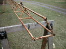
March 16, 2006 / Left to right: top / bottom / center
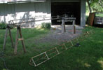
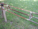
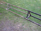
June 17, 2006 / Left to right: preparation / rusted and sanded / sanded and painted / painted (top of tower)
General Antenna Reference
www.packetradio.com/ant.htm
Arrow Antennas
arrowantennas.comTada Communications, Inc.
202 Ridge Road East
Rochester, NY 14621
585-342-0716
Per Lynn (N2IZX) 22-oct-2006 - This outfit can mount antennas on cars. They do commercial work too (antennas on school busses, trucks, etc.)Mosley Antennas
www.mosley-electronics.com
Note the TA-33-JR tri-banderJ-Pole Antennas
Purchased the following two J-pole antennas directly from Leo (ex-AB7ON [cancelled 07/09/2013] / W7OSS as of 22-oct-2013). This was not directly through an eBay auction, because I wanted 20 feet of coax, and the standard antenna in the eBay auction had five feet. Purchased the two antennas for $50.90 on 28-dec-2005. Male BNC connector (screw-on type BNC connector) to 20 feet of RG-58U coaxial feed line to a "dual band" (2 m and 70 cm) 300 Ω twin lead J-pole antenna. One was encased in a three-foot section of PVC pipe, the other was flexible. 27-jun-2006: SWR measured 1.2:1 at 145.11 MHz.Wireman / Antenna Wire, etc.
thewireman.com/index.shtmlWire - thewireman.com/antennap.html
Dacron UV resistant rope - thewireman.com/antacc.html
25-sep-2021 (Saturday): Elmira Hamfest. Got the time off from WYSL, so attending this event only depended on the weather. The day started off clear with temperatures in the mid 40s, and it finally warmed up to 70°. Left home at approximately 0715 in the 2015 Mini Countryman, and ran into dense fog most of the way there. Arrived at the Chemung County Fairgrounds at 0900. Leisurely did the rounds, and left at 1015. There was a clapped-out Johnson Viking Ranger for $250, and a couple of new looking Texas Star 11 meter "foot warmers". for $200 each. Other than that, nothing much really caught my eye. There were some familiar faces, but nobody I knew well enough to talk to. Made last-minute plans (via cell phone) with Kevin N2AFX (ex-WB2QMY) on the way to the event, but he arrived around the time I was leaving, so our paths never actually crossed.
27-sep-2020 (Sunday): East Avon Hamfest on the grounds of the East Avon Flea Market (1520 West Henrietta Rd). Weather was sunny, dry, about 72°. The group that published the information was Upstate NY HAM Radio News & Information. This was my first hamfest since Elmira in September 2017. Heard about it through Kevin (N2AFX - ex WB2QMY), but did not see him at the event. I was working at WYSL, but cleared it with the boss, and took some time off to have a quick look around. Was there from about 7:45 a.m. - 8:45 a.m. The main Avon Flea Market was in progress (a big turn-out), but the hamfest itself was a small gathering. Didn't purchase anything, but had a good rag chew with Don (AB2NM) who was selling (among other things) a nice, working, unrestored, Collins R-390A for $499 (had no cover - was probably rack-mounted). I gave him Bob Harrison's name (W2ICQ) in the Syracuse area because he was looking to have it restored. Also talked briefly with Tim (WB2PAY), and Don (KD2REU) in the flea market area. The official hamfest was taped off under a pavilion, but there were a few other familiar radio vendors hither and thither on the flea market grounds.
30-sep-2017 (Saturday): Elmira Hamfest – Horseheads, NY. Got the day off from WYSL. The flea market started at 0700. Purchased a $6.00 ticket online (via PayPal) on July 24 (gate price was $8.00). Contacted the hamfest hotline (607-301-0040) July 31 to verify when the ticket would be sent. The representative said the tickets would be mailed August 8. As of August 14, the ticket had not arrived. It finally arrived in late August. A member of the hosting club (Amateur Radio Association of the Southern Tier) emailed me to say that the person who normally handled the tickets had died. Left home by myself at 0535 driving my 2015 Mini "Cooper S Countryman All-4" to 28 Liberty Street in Bath, NY for breakfast at the Chat-A-Whyle restaurant. The last hamfest I attended was the same Elmira event in 2015. Brought the ICOM IC-W32A HT with a mag mount on the roof, and worked a few stations on the way to Bath – Tom (W2TF), Tim (WB2PAY), Larry (KD2LGX), and Roy (W2IT). Planned to meet Tim (WB2PAY) at the diner, which we did. Our GPS ETAs were within one minute of each other (mine: 0659, his: 0700). Drove in the dark up until about the time I reached Bath. Had breakfast with Tim, and left for the hamfest around 0750. WX was mostly dry and overcast up to this point. Getting closer to the hamfest, the rain got pretty heavy. Most vendors had covered their wares with plastic sheets, which made viewing and shopping problematic to say the least. Those who had tents or shelters were able to conduct business. Attendance was actually pretty good! Saw only a few familiar faces – hunkering down under an open pavilion were: AWA members Lynn (W2BSN), Dave (N2WZS/SK), and Bruce (W2BDR). Chatted with them briefly. Equipped with an umbrella, wool cap, sweat shirt, and gloves, made a once-around examination of the field, dropped my ticket stub in the cage, then phoned Tim to let him know I was leaving. No purchases were made. Rain was heavy and steady all the way back to Geneva, where I caught the I-90 (Exit 42). From there, the sky cleared, and the roads were dry. Chatted with Larry (W2LB) while driving on the Interstate for a while, and later, while driving through Victor, worked Lynn (N2IZX). The remainder of the day (back at the QTH) was sunny and plesant. The WX situation in Elmira was just an unfortunate problem this year.
26-sep-2015 (Saturday): Elmira Hamfest – Horseheads, NY. The flea market started at 0700. Left home by myself around 0550, and drove my 2008 Toyota Yaris sedan to 28 Liberty Street in Bath, NY for breakfast at the Chat-A-Whyle restaurant. Talked with Tim Brown (WB2PAY) on the Bristol repeater (145.11) on the way there, and met and ate with both him and his passenger Jay Golden (K2JSG). Had a nice eyeball QSO. After breakfast, followed Tim to the Hamfest grounds and arrived around 0830. The WX was fine (early fog lifted, becoming sunny and dry, with highs eventually topping out in the low 70s), attendance and selection were good, but did not buy anything! Saw and chatted with Ed Gable (K2MP), Lynn Bisha (W2BSN) and Andrew Lesny (W2FG - carrying a 1959 Leica M3), Mark Humphrey (K3XY) - the WYSL contract engineer, and Tim Magee (WB2KAO). Packed up around 1150, and followed Tim and Jay to the Beijing Garden in Elmira (145 W Gray Street) for lunch, which was tasety. The GPS routed me through Watkins Glen, up Route 14 to Geneva, and finally to Route 96N to Victor. Traffic was slow and heavy through Watkins Glen, and the numerous wine businesses on Route 14 were busy. Got back to the home QTH by 1510. This was the first hamfest I attended in exactly two years - since starting to work both Saturdays and Sundays at WYSL. I was already working Sundays at WYSL, and picked up the Saturday gig just after attending the September 28, 2013 Elmira Hamfest.
28-sep-2013 (Saturday): Elmira Hamfest – Horseheads, NY. The event started at 6:00 a.m. and ended at 2:00 p.m. Picked up Kevin (WB2QMY) at his home QTH at 6:30. Drove straight through, but stopped for a donut, and a "cuppa" at Dunkin' Donuts in Elmira.
Picked up some coax connectors and small fans. Included a "possible WWII-era", olive drab, Western Electric M-359 (a.k.a. UG-646/U) PL-259-to-SO-239 right angle plug adaptor. Photo of the Western Electric M-359. If anyone can positively date the Western Electric M-359 adaptor, please drop me a line.
Also, an Amphenol (Chicago) M-359A right angle adaptor, a BNC "T" adaptor, a straight BNC-to-SO-239 adaptor, a PL-258 straight adaptor, etc. All adaptor prices ranged from $1.00 to $3.00. Interesting to see the 1958 Allied Radio catalog price for the same adaptors – still $1.00.
Also picked up two new, small, 12 volt fans for $2.00 each. WX started out cool and foggy, but clear skies and temps. in the 70s prevailed.
20-jul-2013 (Saturday): Batavia Hamfest. Route 98 at Alexander firemen grounds (Alexander, New York). Left my home QTH around 0715 and drove (solo) in my 2012 Ford Fusion (company car). Weather was overcast and in the 70s. A lot of rain fell the night before, so the field was soggy. Turn-out was lower than in 2011. About half the field was occupied by vendors. Managed to find five Sam's Photofact sets for German radios – three of which (radios) I already owned. Saw familiar faces and had a few brief conversations. As as I completed Photofact transaction, a heavy drizzle ensued, resulting in many vendors and attendees running for cover and/or leaving. Arrived back home by 1130.
15-jun-2013 (Saturday): Rochester Hamfest (a.k.a. Ham-o-Rama). Held enirely out of doors at R.I.T. in parking lot "S" – behind the main campus. Weather was fine and sunny, with high clouds and temperatures in the low 70s. Met Kevin (WB2QMY) and his friend, Mike (N2IYP) at Jay's Diner at 7:30. Arrived at the hamfest around 8:30. Turn-out was good. Found a mint Johnson Viking Matchbox Model 250-23-3 (with meter) including the remote directional coupler (Johnson p/n 250-37), and original manual (in original envelope). Price was $100. Had lunch inside R.I.T. with Kevin and Steve (KC2YTC). Scanned the flea market one last time, and then drove to the newly opened AWA Museum. I drove my 1966 Mercedes-Benz 250S, and Kevin followed in his car. Roy (W2IT) was on guide duty, and gave us a tour of the new facility.
13-apr-2013 (Saturday): Drumlins Hamfest (Drumlins ARC) / 8:00 - until ? Traveled with Jim (N2VX/SK) and Roy (W2IT). Roy drove his Subaru with new vanity "AWA" license plates (nifty!). Left my QTH at 7:10 and headed to the new hamfest location – the Palmyra VFW post 6778 at 4306 Route 31, Palmyra, NY. Stopped at the Log Cabin (Rte. 31-F Macedon) for breakfast, where we met Kevin (WB2QMY). The WX was cloudy and in the 40s. Back in Mendon by 10:40. Good turnout. Got a vintage, Sears, 5 amp, 6v/12v battery charger (from Ed Gable) for $5.00. Nice to get out, and see familiar faces. Pete (WB2UAQ) led a few of us outside to show off the home-brewed trans-match he had been tinkering with since 1985!
23-feb-2013: (Saturday) Horseheads Winterfest / Horseheads, NY. Rode with Tim (WB2PAY). Met at my QTH at 0600, and stopped for breakfast at "The Villager" in Canandaigua. I made no purchases at the hamfest. Chatted with Lynn (W2BSN) but did not see any other Rochester area hams. WX was dreary with temps. reaching the lower 30s. After the hamfest, stopped at Oak Hill bulk foods (3173 Rte 14A Penn Yan) to get a couple oatmeal "whoopie pies" – a delicious Amish tradition!
26-jan-2013: (Saturday) Lockport Hamfest – Lockport, NY. Doors were open from 8:00 a.m. until noon. Admission $5.00. South Lockport Fire Hall (5666 South Transit Road – north-east of Buffalo). Picked up Kevin (WB2QMY) at his QTH at 0645 where we took my 2012 Ford Fusion (company car) with my Garmin "nüvi 2455" GPS. Stopped for breakfast at Peppermint's in Avon, NY. The hamfest was similar to previous years, but no purchases this time. After the hamfest, we explored a few of the antique stores on Main Street of historic Lockport. Then used the GPS to navigate to Hirsch Radio Supply (a.k.a. Hirsch Radiomart / 219 California Dr, Williamsville, NY 14221 ) and finally, to the original Anchor Bar (1047 Main St, Buffalo, NY 14209) for an order of 20 wings. The waitress accidentally brought an order of 50 wings. Also stopped at Fox Farm Antiques on Route 20 (just west of Avon) on the way back. WX was clear and cold with temperatures in the 20s.
29-sep-2012 (Saturday): Rochester Amateur Radio Association (RaRa) annual banquet held at Burgundy Basin Inn. Price was $15, and since my XYL was out of town, it seemed like a good bargain. Social hour began at 6:00 and dinner was served at 7:00. Food was delicious, and the evening was enjoyable.
29-sep-2012 (Saturday): Elmira Hamfest – Horseheads, NY. The event started at 6:00 a.m. and ended at 2:00 p.m. Traveled with Kevin (WB2QMY). Picked him up at his QTH at 0630. Decent turnout and the weather was cloudy with temperatures in the 60s. Did not make a single purchase. Had breakfast in Bath, NY at the "Chat-A-Whyle" restaurant, and had lunch at "Ruby Tuesday's" in Elmira. Stopped in a few antique and "Junque" shops on the way back.
30-jun-2012 (Saturday) Rochester Hamfest Sponsored by the Rochester Amateur Radio Association. Located at the R.I.T. Gordon Field House. Lots of outdoor flea market activity. WX was hot and sunny with temperatures in the upper 80s. Picked up a mint condition Astron "RS-20A" regulated power supply with original documentation for $50. The vendor was Chris (WA2SPQ),
14-apr-2012 (Saturday): Drumlins Hamfest (Drumlins ARC) / 0800 - until ? Traveled with Jim (N2VX/SK) and Kevin (WB2QMY). We left my QTH in Jim's Saturn at 0730. Weather was sunny and cool (mid-50s). Got a small, used, 12 volt (7 amp-hour) battery ($7.00) for my "Aqua Guide 705" Radio Direction Finder, a roll of coax sealant ($1.00), a metal pulley ($10.00), and a 100' spool of 3/32" diameter, double braided, polyester antenna rope ($10.00). We were back on the road by about 0945.
Afterwards, Kevin helped fix my "drooping" 80 meter dipole antenna by climbing the 40 foot pine tree* and running new rope through a vintage ceramic insulator. A cordless drill made a pilot hole for the insulator. The main problem was the counter-weight (a plastic milk jug filled with sand) disintegrated and broke free, creating about five feet of slack in the system, and the drooping effect. To make matters worse, the original polyester rope was stuck in the top of the tree, preventing that end of the antenna from being lowered, as designed. *Kevin was near the top of the tree in this photo, but invisible – truly a majestic pine tree.28-jan-2012: (Saturday) Lockport Hamfest – Lockport, NY. Doors were open from 8:00 a.m. until noon. Admission $5.00. South Lockport Fire Hall at intersection of Route 78 (Transit Road) and Ruhlman Road. Lockport, NY - near Buffalo. Traveled with Kevin (WB2QMY). Met at his QTH at 0700 where we took my 2008 Toyota Yaris sedan (with a Garmin "nüvi 2455" GPS). Stopped for breakfast at Peppermint's restaurant in Avon, NY. The hamfest was similar to past years. I found a field strength meter (vendor: Bob, N2PWP) with a nice large µA meter, gain control knob, and telescoping antenna (with BNC connector) for $20. Kevin found a nice, used, Garmin "StreetPilot c330" GPS with the manual, power cord, and USB cable for $34. After the hamfest, We used his new GPS to navigate to Hirsch Radio Supply (a.k.a. Hirsch Radiomart) and finally, to the original Anchor Bar, and it worked out well. We ordered a modest "double" order (20 wings) to split, but the waitress accidentally brought a "bucket" (50 wings). In case you have never experienced the Anchor Bar, these wings were presented heaped on a pizza pan with bleu cheese dressing and celery balanced on top of a metal pedestal. Oh well! Also stopped at Fox Farm Antiques on Route 20 (just west of Avon) on the way back. WX was gray and overcast with temperatures in the 30s. It began snowing at about 11:00 a.m. and gradually got worse, but by the time I got back to my QTH, the roads were dry and the sun was out.24-sep-2011 (Saturday): Elmira Hamfest – Horseheads, NY. The event started at 6:00 a.m. and ended at 2:00 p.m. Traveled with Roy Wildermuth (W2IT), Jay Golden (K2JSG), and Bob Hobday (N2EVG). Everyone met at my QTH at 6:00 a.m. and Roy drove his wife's four-door Jeep. Stopped for breakfast at Tim Horton's in Canandaigua. Followed Rtes. 5&20 to 14A south – along the west side of Seneca Lake, and made pretty good time on the 83 mile trek, including a quick pit stop in Watkins Glen. Weather started out cool (50s), damp, and misty. Skies remained heavy and dark, but rain-free all morning. Temperatures mever made it out of the 50s. The hamfest was only about 70% of its 2009 size. Attendance was good, but not as many vendors made the trip as in previous years (some also packed up and left early). We left the hamfest at 11:00 a.m., and had lunch at Applebee's. By the time we got back on the road, the sun was out, and it reached a comfortable 65°. I made no purchases other than three wine bottle corks for $1.00.
10-sep-2011 (Saturday): Rochester Amateur Radio Association (RaRa) Fall Fest & Tailgate Party. Located at the Shriners facility at 979 Bay Road in Webster, NY. Starts at 8:00 a.m. Traveled with Roy (W2IT). Met at my QTH at 0730.
30-jul-2011 (Saturday): Batavia Hamfest. Genesee County Fairgrounds (Route 5 in Alexander, NY). Roy (W2IT) arrived at my QTH at 0630 and we took his vehicle (2010 Jeep with rag top) to the Hamfest. Weather was sunny and in the 80s. Purchased "Everybody's Television and Radio Handbook" for one dollar. Roy picked up a nice Collins S-line receiver, transmitter, power supply, microphone and manuals. Admission was $5.00 and I treated Roy. This was the last hamfest at this location sponsored by the current club. The event was to be held the following year, but by a different organization.
04-jun-2011 (Saturday): Rochester Hamfest and ARRL Atlantic Division Convention. Sponsored by the Rochester Amateur Radio Association. Fair WX to start out with, overcast with a few drops of rain, which tapered off for a while, but turned into a steady drenching by mid-day. Temperatures were in the 60s. Picked up an Astron "RS-20M" regulated power supply (with Volt/Amp meter) for $65. The vendor was Joe (NW2A), and an ICOM "IC-2100H" 2-meter VHF FM transceiver including the operating manual, "HM-98S" microphone, mounting bracket, and power cords for $80. The vendor was Jerry (KB2QIU). Here is a photo of the Astron RS-20M with the ICOM IC-2100H. Met some friends and had a nice morning. Was back at the QTH by 1100. The power supply and radio worked fine.
19-20-21-22-may-2011: Dayton Hamvention / Hara Arena - Trotwood, Ohio. Traveled to Dayton with Lynn (W2BSN) and Jay Golden (K2JSG). Left on Thursday May 19 and returned Sunday May 22. Weather was sunny and warm with highs in the 70s. Not much to report except I found some paper manuals to complete my Grundig "Yacht Boy 400" set.
26-feb-2011: (Saturday) 30th Annual Horseheads Winterfest / Horseheads, NY. Got my ticket ($5.00) at the February RaRa meeting. Rode with Kevin (WB2QMY). Met at his QTH at 0630. WX was cold (about 17°) and overcast. Another 7-10 inches of snow fell Friday, but roads were relatively clear by Saturday morning. Stopped for breakfast at the "Farmer's Kitchen" in Wayland.
The hamfest was smaller than in previous years, and the second room of the armory was not open. Saw Tim (WB2PAY) and Tim (WB2KAO). Did not find anything worth buying. We had lunch with Roy (W2IT) and Lynn (W2BSN) at "Ruby Tuesdays" in Elmira.
June 5, 2010 (Saturday): Rochester Hamfest and ARRL Atlantic Division Convention. Sponsored by the Rochester Amateur Radio Association. Good WX, with a few drops of rain. Temperatures in the 70s. Picked up antenna rope, bungee cords, and a few 1940s magazines.
27-feb-2010: (Saturday) 29th Annual Horseheads Winterfest / Horseheads, NY. Got my ticket ($5.00) at the February RaRa meeting. Planned to travel with Jim (N2VX/SK). A heavy snow storm from the previous two days was tapering off. We left my QTH at 0640. Got as far as I-390 in Rush, and decided the conditions were too treacherous to make the 100+ mile trip. Only one lane was open on I-390.
26-sep-2009 (Saturday): Elmira Hamfest. Horseheads, NY. Traveled with Tim (WB2PAY) and Jim (N2VX/SK). Gathered at my QTH and left at 0637. Tim drove his 2000 Suburban. We stopped for breakfast in Canandaigua. The weather was partly overcast with breaks of sun early, then overcast and mild (about 65°). It became breezy, and vendors began packing up around 1130 because of the possibility of rain. It remained dry the whole way home. Picked up a German-made pocket volt meter with leather case ($20), a reactance slide rule calculator with original envelope ($6.00) and an Ohmite Ohm's Law slide rule calculator with original envelope and instructions ($3.00). Also snarfed two "international photo technik" [sic] magazines (No. 1 1960 and No. 3 1960) courtesy: Lynn (W2BSN). They included photos of period Mercedes-Benz Type 300 "Adenauer" limousines and a Type 220S Ponton sedan. Also grabbed an old hard shell attaché case courtesy: Tim (WB2PAY).
01-aug-2009 (Saturday): Batavia Hamfest. Genesee County Fairgrounds (Route 5 in Alexander, NY). Lynn (W2BSN) and Roy (W2IT) arrived at my QTH at 0630 and we took my car (1989 Mercedes-Benz 260E) to the Hamfest. Weather was sunny and about 80°. Purchased six back issues of Electric Radio.
May 30, 2009: (Saturday) Rochester Hamfest (75th Anniversary Edition) and ARRL Atlantic Division Convention. Sponsored by the Rochester Amateur Radio Association. website: www.rochesterham.org. or click here Rochester Hamfest Talk-In: 146.79 (PL 110.9). Contact: Len Crellin, KC2PCD, c/o RaRa, PO Box 93333, Rochester, NY 14692. Email: kc2pcd ]at[ rochester.rr.com. The Hamfest is located at the Barnard Carnival Grounds, 380 Maiden Lane, Rochester
28-feb-2009: (Saturday) 28th Annual Horseheads Winterfest / Horseheads, NY. Traveled with Kevin (WB2QMY) and Frank (WB2PYD). 0700: Met Kevin at his West Bloomfield QTH. We arrived at Frank's QTH (Swain, NY) around 0815. Got to the Hamfest around 0930. The weather started out cold (17°) and overcast. When we got to Swain, it was only 12°, but it was sunny for the rest of the day. Hamfest attendance was good. Saw: Bruce (W2BDR), Herb (K2VH), Lynn (W2BSN) and Tim (WB2PAY). Talked about ARC-5 military transmitters with Bob (N2RIC)*. Bought 100' of double braided (3/32") polyester antenna rope for $10 (Synthetic Textiles, Inc). Made donation ($5.00) for the children of N2HLT/SK. Lunched at Ruby Tuesdays in Elmira with Kevin and Frank ($12.00). Arrived back at home QTH by ~16:20.
*On April 13, 2010, Bob Hoppe (N2RIC) (from Waverly, NY near Horseheads) became a SK at age 71. I enjoyed talking to him at AWA functions in Rochester and Bloomfield - and hearing him on the air with his ARC-5 transmitter/s on the Sunday afternoon AWA AM Net (3.837 MHz). He seemed too fit and young to pass away.
31-jan-2009: (Saturday) Lockport Hamfest / Lockport, NY. Doors open from 8:00 a.m. until noon. Admission $5.00. South Lockport Fire Hall, Route 78 & Ruhlman Road. Lockport, NY - near Buffalo. Traveled with Lynn (W2BSN).
05-nov-2008: (Friday) RaRa Auction / Henrietta, NY. Small, but well attended. Auction started at 7:30 p.m. Lots of items, bidding was slow at first. Did not purchase anything.
27-sep-2008 (Saturday): Elmira Hamfest. Purchased my ticket ($5.00) on Friday September 5 at the RaRa meeting. Otherwise, tickets were $6.00 at the gate. Jim (N2VX/SK) picked me up at 0605 and then we picked up John (KG2NI) in Henrietta. We stopped for breakfast in Corning. It rained the whole time. Picked up a circa 1973 Sony AM/FM stereo tuner model "ST-80W" (for $2.00) and a plastic AM transistor novelty radio in the shape of a 1963-1964 Cadillac convertible ($8.00). Also found some black plastic battery holders I had been looking for (holds three AA batteries each) for $1.50 each (purchased two).
09-aug-2008: (Saturday) KLARA Hamfest (Keuka Lake Amateur Radio Association). Located on the grounds of the "Howard Community Building" at 7481 Hopkins Road in Howard, NY. Talk-In frequency was 145.190 (no PL) but the station was silent when I called. I discovered the hamlet of Howard is nestled in the middle of a corn field between Hornell and Bath about 60 miles south of Rochester. Drove solo using Mapquest directions. Shot down Rte 64, to Rte 65, to County Road 37, down along the west side of Honeoye Lake (the high road, not the lake road) through Springwater (Route 15) and Italy Valley, and came out in the middle of the boondocks somewhere. Real nice scenery, and I only got lost once or twice. I made the 51 mile drive from my home QTH in roughly 60 minutes. The weather was sunny and pleasant (about 73º). The Hamfest was small, but they provided a hearty breakfast. I had the eggs, sausage, coffee and orange juice. Pancakes were optional. All that food for the price of a donation. What was the purpose of the trip again? Oh yes, radios. Right off the bat I found a mint 1967 Hallicrafters model "S-120A" receiver, which I got for $25. This was an unusual Hallicrafters model because it was made in Japan. So, this little treasure made the trip worth my while.
19-jul-2008: (Saturday) Batavia Hamfest / Located on Route 98 about ½ mile south of Alexander, NY. Alexander Firemen's Grounds. Sunny, hot (about 90º) and humid. Breakfast started at 07:00 (did not attend), and the fabled chicken bar-b-que commenced at 1100 (too hot to attend this either). The flea market was down considerably from 2006. Purchased a Fasco squirrel-cage dual fan assembly ($7.00), a 12 volt wall-wart ($2.00) for use on the ICOM 260A, and a set of old style headphones with ¼" plug ($2.00). Also bought a small circuit board (1"x1") with a few components on it for $0.10. I offered him $0.05, but he held firm on the price. This item will make a nice Christmas Tree ornament. Traveled to the Hamfest with Lynn (W2BSN). Breakfast at Papa Jack's in Victor, lunch at the American Hotel in Lima.
30-31-may-2008: (Friday / Saturday) Rochester Hamfest / Rochester Hamfest / Rochester, NY. Friday was sunny and about 70º. Did not go back on Saturday, but since I was newly elected to the RaRa board of directors, went to the dinner banquet on Friday night. Friday in the flea market, I got a vintage (circa 1950s) Olson model "SW-134 Telegraph Key with Buzzer" (powered by 1 D-cell) for $8.00. Included was the original box, in very good condition. Also got a set of old Trimm Featherlight (Libertyville, Illinois) headphones (for another $7.00). The headphones had the correct style connector pins to mate with the vintage buzzer assembly. Found a copy of the book, John Lennon - In His Own Write for $18.00. One never knows what they might find at a hamfest! The original copyright was 1964, by Simon & Schuster. Afterwards, I learned that the going price on eBay was about $8.00, and this particular book was printed by Lennon's estate so, basically, I paid too much. The vendor for said items was, Jerry (KB2QIU). Also got a copy of 200 Meters and Down - The Story of Amateur Radio for $11.00. New condition, soft cover (via a literature vendor inside the Dome Arena). Sold a Realistic DX-150 radio for $35.00 (paid $45 at the 2008 Elmira Winterfest back in February) and also sold a Hallicrafters model "S-38 C" for $20.00 (paid $19 at the AWA Spring Meet Auction on May 3, 2008). Sold the radios from Tim's (WB2PAY) flea market space.
16-17-18-may-2008: Dayton Hamvention / Hara Arena - Trotwood, Ohio. Traveled to Dayton with Lynn (W2BSN) and his brother, Milton "Mick" (ex-KN2HWL). Weather was sunny, breezy and about 65 degrees both days (Friday / Saturday). Items purchased are listed here.
19-apr-2008: Drumlins Hamfest (Drumlins ARC) / 08:00 - until ? Very nice weather. Sunny, about 65 degrees. Lots of activity and familiar faces. Bearcat IV crystal scanner ($5.00), 110 Vac fan with line cord ($10.00), and two BNC-to-SO239 adapters ($1.00 each).
23-feb-2008: (Saturday) 27th Annual Horseheads Winterfest / Horseheads, NY.
26-jan-2008: Lockport Hamfest / 0800 - 1200 / $5.00 / Travel with Tim (WB2PAY) and Lynn (W2BSN).
02-nov-2007: RaRa Auction / Henrietta, NY. Small, and well attended. Auction started at 7:30 p.m. on a Friday. Lots of items, bidding went slowly. Purchased a 1955-1962 E.F. Johnson "Viking Valiant" AM/CW transmitter.
29-sep-2007 (Saturday): Elmira Hamfest. Nice turnout and a lot of vendors. Sunny and warm (60s). Got a NOS EM80 vacuum tube ($3.00) to have on hand as a spare. The Telefunken "Opus 7" uses this "magic eye" tube. Also go an old vacuum tube booklet, "Radio Tube Hints" (Sylvania - 1943) ($1.00), and finally, a Hallicrafters S-40 short-wave receiver (excellent condition) ($125.00).
01-02-jun-2007: (Friday / Saturday) Rochester Hamfest / Rochester, NY. Friday, the weather was warm and sunny. Saturday, the weather turned quite warm (84 degrees) and sunny.
18-19-20-may-2007: Dayton Hamvention / Hara Arena - Trotwood, Ohio. Rode to Dayton with Tim (WB2PAY) on Thursday 17-may-2007 and return on Saturday 19-may-2007. Sunny and warm with temps around 65-70 degrees.
24-feb-2007: (Saturday) 26th Annual Horseheads Winterfest / Horseheads, NY. Sunny, but cold (15° F). The event was smaller than last year, but attendance was good. Parking was a problem. Specifically, the lack of spaces, due to inability to park on grass because of deep snow and snow banks along the entrance road. I did not purchase anything. Admission $6.00.
30-sep-2006: (Saturday) 31st Elmira International Hamfest / ARA of the Southern Tier / 08:00-14:00 / Talk-In: 147.360 (no CTCSS Tone) / Horseheads, NY / Chemung County Fairgrounds. Weather was overcast and cool. Nice turnout.
18-sep-2006: Visit and tour W1AW (ARRL Headquarters) / Newington, CT.
17-sep-2006: (Sunday) Candlewood Amateur Radio Association Hamfest. Edmund Town Hall. Route 6, Newtown, Connecticut. 0830-1230. Admission $5.00. Mild and overcast. A small hamfest in a parking lot with some vendors inside the town hall building as well. Refreshments and lectures (technical, radio topics) inside.
29-jul-2006: Batavia Hamfest / Located on Route 98 about ½ mile south of Alexander, NY. Sunny, about 80 degrees, good crowd. The only purchase I made was a 1963 Telefunken "Jubilate de Luxe" (Type 5461 W) AM/FM/SW table-top radio ($40). It was in fine condition.
02, 03, 04-jun-2006: Rochester Hamfest / Monroe County Fairgrounds (and Dome Arena) / Rochester, NY. Took Friday off from work (02-jun-2006) and returned on Saturday. Friday was sunny, warm (76 degrees) and dry, but Saturday was dark, cool (65 degrees) and raining. On Friday, I found a vintage (1960-1962) Allvox-Strahler (Telefunken) RS1, RS2, or RS3 hi-fi loudspeaker for $5.00. It features an oval shaped cabinet with teak veneer, and a grille cloth that wraps around the entire cabinet. The top and bottom of the speaker cabinet are accented with brass colored trim. The Telefunken logo is at the bottom of the speaker grille. Has three brass "button" style feet. Original, European style speaker connector was missing. Drivers feature AlNiCo magnets. The speakers are about 5.5" x 6.5." Also bought a Westcom (designed by Astron / Irvine, California) linear power supply model RS-12A (9A continuous output) / $20.00 from Ed Gable (K2MP) (curator of the world famous AWA museum in Bloomfield, NY). Astron still sells this model, new, for $79. Replaced the power cord and adjusted the output voltage from 15.5 Vac down to 13.8 Vdc. Works like a charm and powers up the ICOM 2100H mobile rig that I am borrowing (from Tim WB2PAY) for the "Tour de Cure."
01-apr-2006: Drumlins Hamfest / Newark, NY. (Route 96 to Route 88 north to Newark). Small, but well attended. No snow, cloudy and about 40 degrees.
26-feb-2006: Horseheads Winterfest / Horseheads, NY. Medium sized and well attended. No snow, sunny, but cold, about 30 degrees.
28-jan-2006: Lockport Winterfest / Lockport, NY. No snow, sunny, but cold, about 30 degrees. A small, but well attended event.
04-nov-2005: RaRa Auction / Henrietta, NY. Small, and well attended. Auction started at 7:30 p.m. on a Friday. Lots of items, bidding went slowly. Became too late to stay for the misc. items such as literature, etc.
Summer 1989: Family friend, Bob Dengler (KC2QS/SK ex-WB2KDW) demonstrated how to work DX from his mobile rig (inside his new, air conditioned Lincoln Continental Town Car). He worked Europe (France) from Livingston County (Conesus Lake) on what looked like a Kenwood rig. Bob was an interesting fellow, with a dry sense of humor, and many entertaining stories. With regret it was announced that Robert Dengler KC2QS, was reported a Silent Key in the October 2000 edition (Vol. 53, No. 2) of the RaRa Rag published by the Rochester Amateur Radio Association.

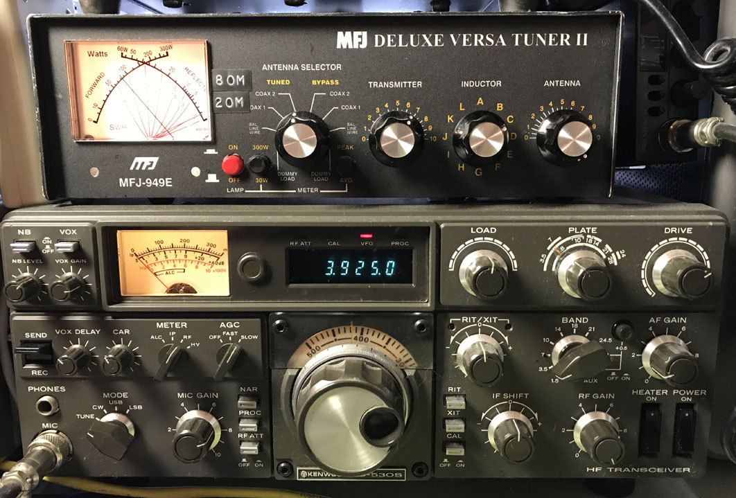
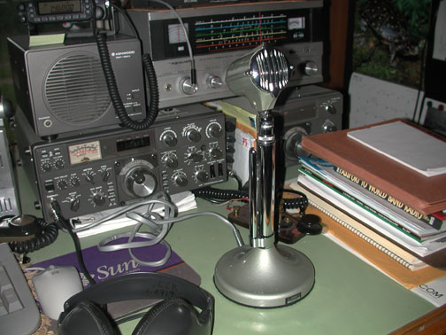
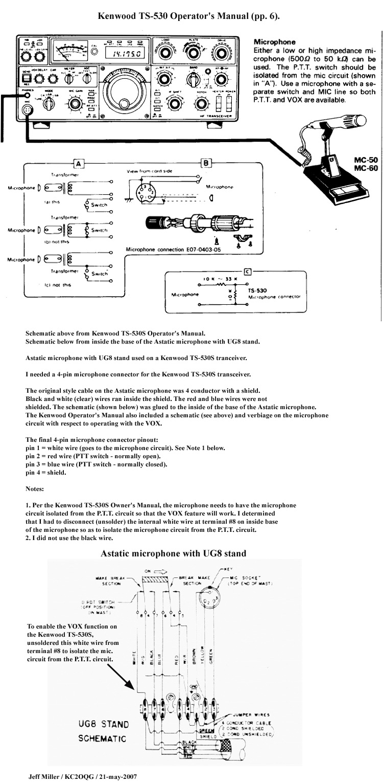
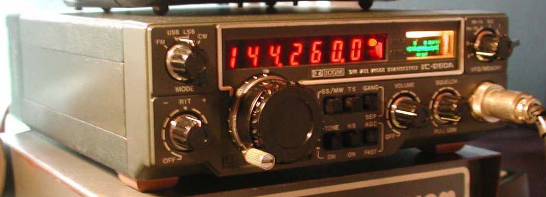
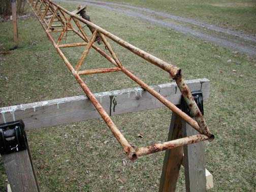
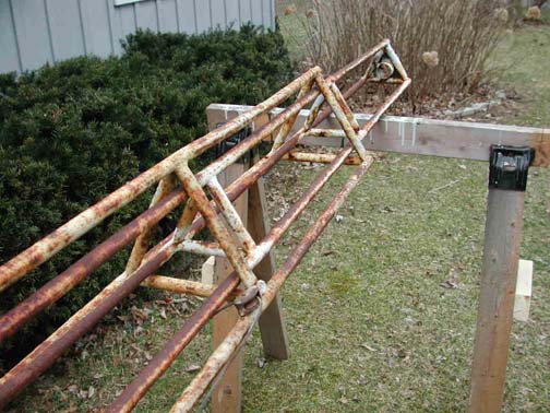


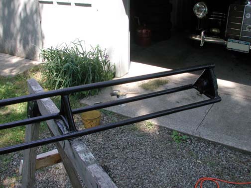
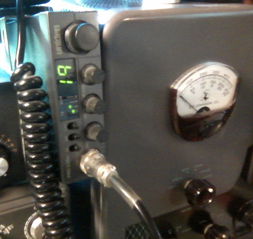
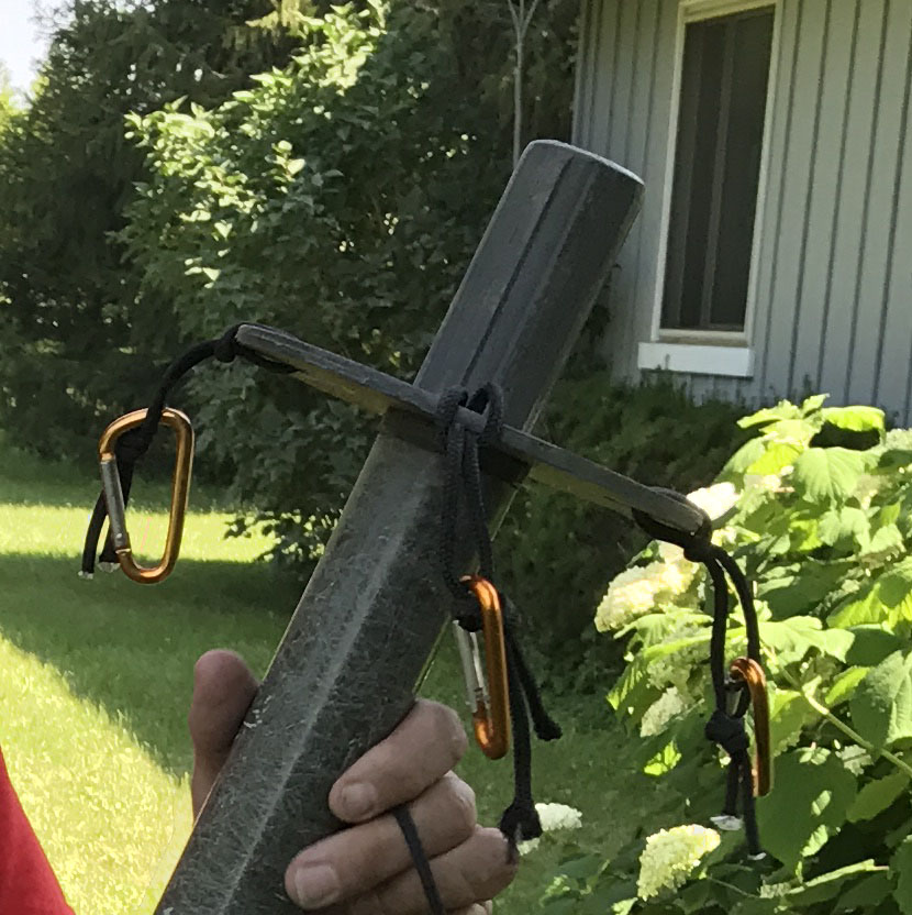
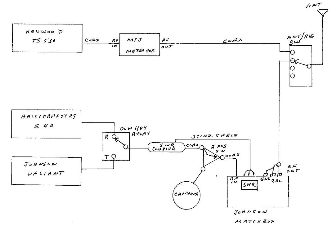
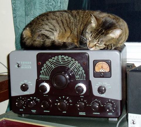
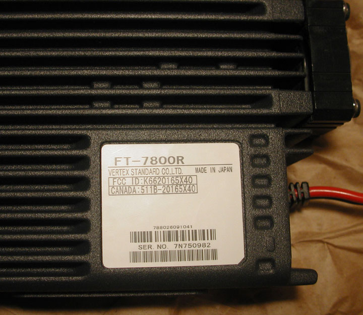
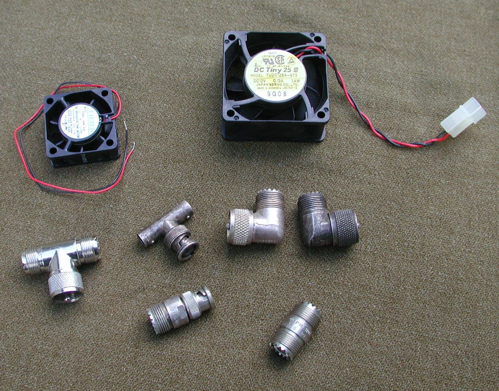