1955-1962 E.F. Johnson "Viking Valiant"
AM/CW Transmitter
This page chronicles repairs made to an E.F. Johnson "Viking Valiant" AM/CW Transmitter.
Latest revisions are at the bottom of the page.
Contents
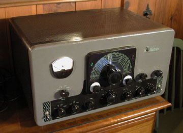
1955-1962 E.F. Johnson "Viking Valiant" (Serial Number 28819)
AM/CW Transmitter (160 to 10 meters)
History
On Friday evening, November 2, 2007 I attended the annual RARA
(Rochester Amateur Radio Association) auction to bid on this circa 1955-1962
E.F. Johnson "Viking Valiant" AM/CW transmitter. After making several must-have
bids, I finally got it for $325, thus adding "AM mode" to the ham shack in a
hefty (83 lbs.), retro style.
The plan was to use it with a 1946
Hallicrafters S-40 receiver, but I still needed an antenna relay (a.k.a.
"Dow
Key Relay", or "T/R switch") to toggle the antenna between the transmitter and receiver.
As a result of some fast networking, an Alliance T/R switch was sourced.
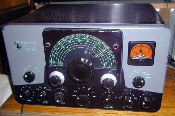
I originally
considered the less powerful (but aesthetically pleasing) Johnson "Viking
Ranger" transmitter but was persuaded by a couple of AM veterans (including K2MP) that the extra punch
of the Valiant would come in handy to break those DX pileups down into Pennsylvania and
even out to Maine (hi hi).
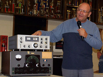
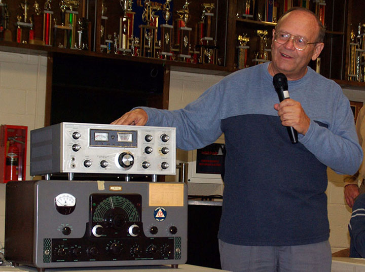
November 7, 2007 / RARA auctioneer and historian, Ed (K2MP)
with the ex-K2JD Viking Valiant.
The radio on top is a Yaesu FTDX-400. Photo
courtesy: Len (KC2PCD).
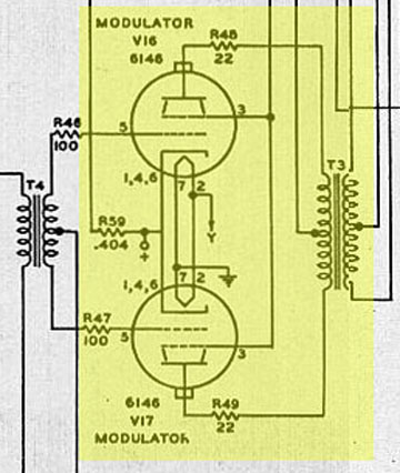
The Valiant has three Type 6146 output tubes modulated by
two Type 6146 tubes.
This Valiant transmitter was originally part of the RARA club station (K2JD)
located
at 111 Westfall Road. Auctioneer and historian, Ed Gable had
this to say about the radio's history:
"The set was purchased by the County of Monroe (New York) for RACES (Radio
Amateur Civil Emergency Service) in the mid 1960s.
The Radio Officer was Charles "Chuck" Brelsford (K2WW) 1. The Valiant was used as the
NCS (Net
Control Station) on the NY Counties 75 meter CD (Civil Defense) Net. It was first used
in the radio room in the basement of the County Hospital at the corner of Westfall
Road and East Henrietta Road."
There were two crystals in the radio when I got it home from the auction. A Type FT-243 (3745 kc), and
a Type HC6 (3730 kc). I subsequently (15-jan-2008) got a Type FT-243 (3837 kc)
for use on the AWA AM Net. The FT-243 3837 crystal came from Brian (AF4K/SK).
Specification Overview
Serial number: 28819
Type or Cat number: 240-104
This particular "Viking Valiant" was Factory-wired, as verified by the rivets at the back of the cabinet.
Modes: AM/CW
Bands: 160 - 10 meters
Input Power: 200 watts (AM), 275 watts (CW)
VFO: Internal
Power Supply: Internal
Final Tubes: ( 3 ) 6146 parallel
Modulator: ( 2 ) 6146 push-pull
New Price: $349.50 (kit) / $439.50 (wired)
Years Produced: 1955-62
Size: 11 5/8" high x 21 1/8" wide x 17 3/8" deep
Weight: 83 lbs.
Schematics and Manuals
Fuses
- F1: 1.5A 3AG (inside the chassis on the rear edge). Protects circuits associated with low voltage supply (T2).
- F2: 8A 3AG (in the AC plug)
- F3: 8A 3AG (in the AC plug)
Pilot Lamps (VFO dial, power, etc.)
To replace the pilot lamps, it was necessary to remove four long, 14" (actually: 13 13/16") 10-24
round-head bolts and star washers from the rear of the cabinet. Also removed twenty short (½", 10-24,
round-head) bolts at the back of the cabinet. Slid the chassis out the front of the
cabinet to gain access to all pilot lamps (bulbs).
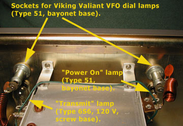
- Type 51 (bayonet base). Three required. The "power on" lamp shines through
the green lens to the left of the VFO. There are also two Type 51 bulbs for the VFO dial
illumination. Available from the usual antique radio supply stores (Radio
Daze, etc.).
- Type 6S6 (120 volt, screw base). One required. This lamp comes on when
transmitting, and shines through the red lens to the right of the VFO.
Possible sources included Home Depot, or any number of electrical supply
stores. online sources were Ken's Electronics, and The Bulb Man, among others. The usual
antique radio suppliers (Radio Daze, AES) did not carry the Type 6S6 (120 v) bulb. I got mine
from Glenwood Sales, which went out of business in 2008. See Table 2.
Notes: (parts / repairs / manuals, etc.)
Most of these links were used to gather information about the transmitter before work
began in earnest.
-
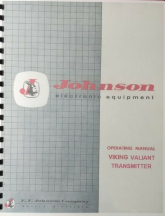
- Viking Valiant
Transmitter Operating Manual Note: Tuning
Procedure begins on p.13 (p.19 of the PDF).
-
Viking Valiant Transmitter Assembly Manual
- AM Transmitter Notes
- AMfone Forum: www.amfone.net/Amforum/index.php
- AMfone Forum: My tune-up question
- AMfone Forum: My "Vac on the chassis" question
- AMfone Forum: My
"low modulation" problem
- Cabinet hardware: Short (½") 10-24 round-head machine screws (20) and star washers.
- Cabinet hardware (original): Extra-long, 14" (actually 13 13/16"), 10-24 thread, round-head bolts (4). Sometimes advertised
at back of Electric Radio Magazine
- Cabinet hardware (replacement): Extra-long (14"), 10-24 thread, pan-head bolts.
McMaster-Carr part number: 99117A610.
Description: Extra-Long Pan Head Combo Drive Machine Screw 10-24 Thread, #2 Drive, 14" Length.
Price: $9.29 (package of 5) plus shipping.
- Cabinet refinishing: Chuck Hurley (K1TLI).
- Crystal (Type FT243): 3.837 MHz (AWA AM Net)
- Crystals (xtals): "FT243" style xtals for Viking Valiant transmitter. Could
use 3.835 MHz xtal for AWA AM Net.
- Dow Key Relay (T/R switch): An antenna switching relay that switches transmitter and receiver between a single antenna feed line.
- E.F. Johnson Transmitter Model Overview: www.radioing.com/museum/tx4.html
- E.F. Johnson Viking Valiant modifications (for consideration): amfone.net/ECSound/Valntmods1.htm
- E.F. Johnson Viking Valiant Photo
- RF "Dummy Load" References: MFJ products
- Microphone, high impedance (Astatic "D-104", or similar). Viking uses an
Amphenol microphone connector with a dual soldered dot in the middle (dual because of PTT).
New crystal elements are available from Mouser (part
number 25LM024). Description: 2" diameter, 0.65 height, 50-8k Hz
frequency response, 9k Ω impedance, -55 dB sensitivity. Manufactured by
Kobitone. Price: $5.26 (as of December 29, 2007).
- Manuals & Schematics: Bought reproduction from eBay
- Manuals & Schematics: Downloaded .pdf from Bama mirror site
- Manuals & Schematics: Copied select pages from Johnson manual at AWA Annex
- Manuals & Schematics: Sam's Photofact does not exist for this radio.
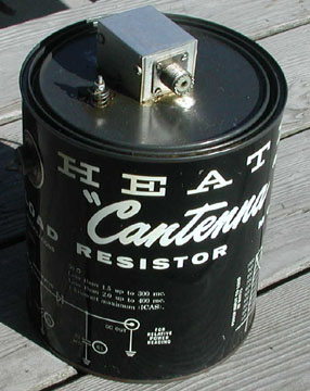
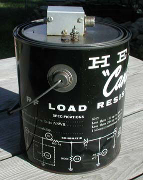
RF Dummy Load
To "tune up the finals" without sending the signal over the air, an "RF dummy load"
(50 Ω impedance) should be used. Originally, the "paint can" style wet dummy loads
(reference: Heathkit
Cantenna HN-31)
were filled with transformer oil (dielectric oil). In the 1960s, transformer oil contained
PCBs (polychlorinated biphenyls). Most PCBs were manufactured as cooling and insulating
fluids for industrial transformers and capacitors. PCB production was banned in the
1970s due to their high toxicity.
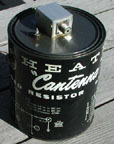
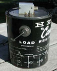

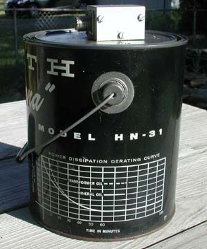
Heathkit Cantenna model HN-31
In lieu of transformer oil, mineral oil could be used. The only difference is when the
dummy load is being used at maximum power ratings. The transformer oil will keep the
load cool for a longer period of time than the mineral oil. Figure about 50% less
time at maximum ratings. Reference the
power dissipation derating curve on the side of the Cantenna for details.
Repair History
November 3, 2007 (Saturday):
Cleaned the exterior and removed some old masking tape, scotch tape, tuning notes
(typewritten) and a CD (Civil Defense) decal. The decal was peeling off anyway.
It said, "Monroe County" at the top, and had the CD logo in the center
and said, "New York" at the bottom. It had another decal which
read, "9332", "Property of County of Monroe." This certainly
was part of the history and patina of the radio, but my feeling was that
whomever
applied those decals 40 years earlier, did so with a legitimate purpose,
but essentially defaced the original appearance of the radio.
November 5, 2007 (Monday):
The public library did not have the manual for this transmitter. So, I
purchased a re-print of the Viking Valiant manual from eBay. Price was $11.95 plus $6.00 shipping.
The vendor's description of manual was,
"Reproduction of the factory Operation Instruction (service)
manual for the E.F. Johnson Viking Valiant amateur radio transmitter. This transmitter
was a very nice performer on 160-10 meters, using three 6146s for the final output amplifier.
It ran 275 watts on CW, 200 on AM phone. The Valiant was renowned for its stable built-in
VFO, TVI suppression, its powerful signal, and its splendid sharp audio quality on AM.
Includes pertinent diagrams and/or photos, installation and connections, operating
instructions for all controls, a complete parts list, tube placement chart, easily
readable schematic diagram to identify all parts, assistance vital to maintaining,
repairing and operating this transmitter. Printed on high quality acid-free bond paper
size 8 1/2" x 11", bound in a water resistant binder. This is a heavy manual, so I
apologize for the higher shipping costs, but it's worth it."
The guy had good feedback,
so I bought a copy to see what kind of "high quality" he was talking about.
Note his description focuses mainly on the radio, and does not describe the
quality of the text or images. Beware!
Unfortunately, the quality of the printing and images was about
average and similar to the .pdf files which were available from the BAMA mirror
website/s for free. I would have done much better to make
copies of the original manual at the AWA Annex. I did in fact make copies of the
original manual at the Annex for the pages that were most difficult to read.
Also downloaded manuals & schematics (.pdf format) from the
BAMA mirror site.
Some of the images (photos) were unreadable. Most of the text was fine.
November 6, 2007 (Tuesday):
Spent the day at the AWA Annex. Got an antenna relay and plug (see photo).
Also made some photo copies of selected pages from the Johnson Viking Valiant
manual.

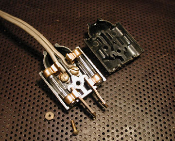
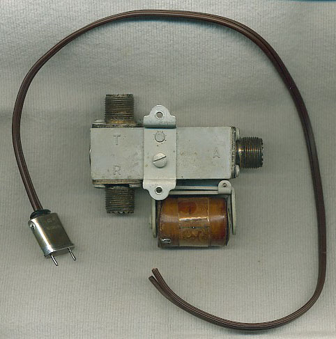
110 Vac antenna switching relay (before restoration) and power
plug
Antenna switching relay (110 Vac) and power plug made from an HC6 crystal
case, and zip cord (courtesy: W2BSN). Note the relay SO-239 connector designations:
"T" (transmitter), "R" (receiver), and "A" (antenna). The "HC6" power plug mates with a
socket (J4) on the back of the radio, and the brown zip cord needs to be soldered to the tabs of
the relay coil (one tab is visible in photo). The bracket with the holes is for mounting
the relay to the rear of the radio cabinet. When the transmitter is keyed, the socket at
the back or the radio supplies 110 Vac for the purpose of energizing the relay
coil and pulling the contacts in so that the transmitter is connected directly
to the antenna feed line. When the operator is finished transmitting, the relay
coil is de-energized (the 110 Vac drops out) and it goes back to its normal state, which is to
connect the receiver directly to the antenna feed line. I tested the relay on
December 31, 2007 and it worked fine. It performed somewhat less than perfect in
action however. I cleaned the SO-239 connectors with silver polish, cleaned the
contacts with fine sand paper, lubricated the pivot point, and bent the center
pole (the moving contact) of the relay as to make it work 100% of the time.
November 8, 2007 (Thursday):
Spoke with Bob Harrison (W2ICQ) on the phone. He has a lot of experience
with these particular radios and is willing to help out if needed. He sent a "mode" knob
with a white "dot" insert. Price: $5.00. Bob lives near Syracuse, NY.
November 11, 2007 (Sunday):
Carried the 83 pound Valiant down to the "operating theater" and
changed the two 10A 3AG fuses (F2, F3) which were in the AC plug with the correct value, 8A
3AG fuses.
AC plug with correct 8A 3AG fuses installed


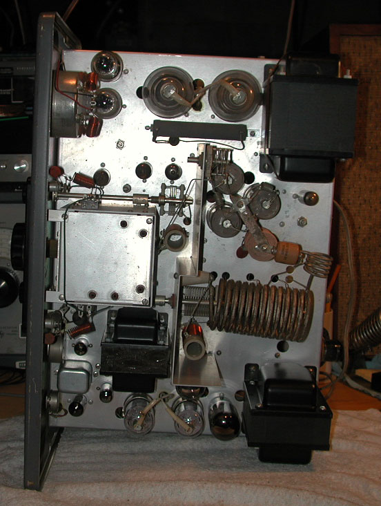
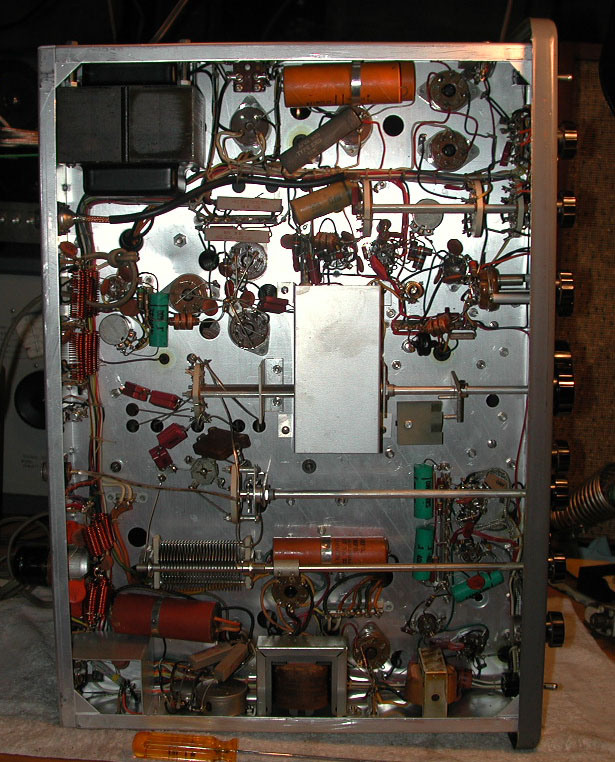
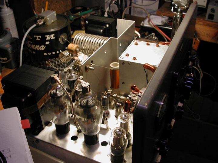
Top (left) and Bottom (right) of Johnson "Viking Valiant"
chassis
Removed three long, 14" (actually: 13 13/16") 10-24 round-head bolts and star washers from the rear
of the cabinet. There were supposed to be four bolts, but one was missing. Also removed
nineteen short (½", 10-24, round-head) bolts at the back of the cabinet. There were supposed
to be twenty, but one was missing. Slid the chassis out the front of the cabinet. The
14" long
round-head bolts were supposedly available through vendors listed in the back of Electric Radio
magazine, but I struck out there. I soon located them on the McMaster-Carr website. The short round-head machine screws and star washers were available
at Debbie Supply.
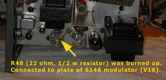
After removing the chassis, I did a quick visual inspection and noticed some melted shrink tubing
(see photo) connected to the plate
of one of the 6146 modulator tubes (V16). It revealed a burned resistor (22 Ω, ½ watt, carbon, 10%).
The resistor (R48) is part of a parasitic suppressor and can easily be fixed.
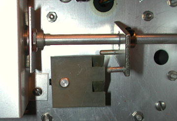
Also noted the band switch arm (D1) was binding on the internal cam (D2) (see photo) that
switches the three VFO tank circuits (three separate frequency ranges) by way of the planetary drive assembly
(D3) (not shown in photo). The first band switch
position is for 160 and 80 meters. The band switch will activate the cam D2 (and the second VFO circuit)
for 40, 20, 15, and 10 meters. A third cam position is used for 11 meters. The band switch (SW3) only
had a few clicks before it hit the cam, but without rotating the cam. The photo shows the tines
(fingers) of the band switch drive arm (D1) which are supposed to engage and rotate the cam (the square "E" shaped
gray thing), but the cam was frozen. Lubricate the cam shaft from the bottom, or by removing the side
cover of the VFO box.
November 16, 2007 (Friday):
Purchased cabinet hardware: Extra-long (14"), 10-24 thread, pan-head bolts.
See Notes.
November 25, 2007 (Sunday):
Replaced resistor R48 (22 Ω, ½ watt, carbon, 10%).
Tried to free up the band switch (SW3). The cam lobe would not rotate when
the knob was moved to different positions. Removed the left side of the VFO
enclosure and sprayed some contact cleaner-lubricant on the switch to no avail.
Also dripped some penetrant (Liquid Wrench) on the camshaft from under the
chassis. The entire switch assembly finally broke loose, but the wires inside
the VFO enclosure were moving along with the switch and they might have broken.
So I removed the cam lobe with a hex (Allen) key, and tightened the nut so the
switch assembly would not rotate. Let sit overnight and try again tomorrow.
December 4, 2007 (Tuesday):
Took the day off from work and went to the AWA Annex. Several of the guys tried
to free up the band selector switch to no avail. The switch did begin to move
when two 250 watt soldering guns were placed against the shaft of the switch.
But as soon as the shaft cooled it would freeze up again. I expect that it will
require more heat (possibly a small butane torch) to free it up.
December 6, 2007 (Thursday) 19:00:
Went to Lynn's QTH (W2BSN)
and freed up the band switch. Talked to Chuck (K1TLI)
earlier in the day via email, and he suggested removing the small circular
retaining ring at the base of the switch shaft. I had not noticed the retaining
ring prior to his message. Believe it or not, removing that retaining ring was the
key to solving the frozen band switch problem! Many thanks to both Chuck and Lynn on
this one.
Removed the
square cam (D2) first. Gently removed the small circular retaining
ring that is around the base of the switch shaft, on the underside of the chassis. An awl or the
edge of a small screwdriver will work. First, we applied some heat from a small
butane torch, which has a small, controllable flame. Then, using a Q-tip, apply some penetrating oil on the shaft
where the ring was removed. Use a small "vice grip" pliers to work the shaft back
and forth, and up and down to free it up. If it moves up or down too
much, the ball bearings can fall out of the switch on the top side. You can
get them back in place, but it takes some patience. The circular retaining ring
was blocking any lubricant from getting down into the shaft and that is why all
previous attempts to lubricate it failed. The retaining ring needs to be removed
first! When it is free simply take a pair of needle nose pliers
and reset the ring by squeezing it. You can use this same procedure on any
rotary switch.
Reset the cam block (D2) so that the band selector knob on the front panel
lines up correctly with the switch. The positions for 160, 80 and 40 meters are
at one VFO switch setting. Positions for 20, 15 and 10 meters are at the second
VFO switch setting, and 11 meters is the third setting.
Skip to Repair History, Continued...
Table 2 (part I)
Replacement Parts for E.F. Johnson Viking Valiant
Compiled: 13-nov-2007 through xx-xxx-200x. Placed order: multiple days
Vendor 1 (for reference): RD (Radio Daze) - www.radiosupply.com
Vendor 2 (for reference): AES (Antique Electronic Supply) - www.tubesandmore.com
Vendor 3 (for reference): MC (McMaster-Carr) - www.mcmaster.com
Vendor 4 (for reference): M (Mouser) - www.mouser.com
|
| Schematic part number |
Value (original) |
Original component and composition |
Value (replacement)
|
Composition of new part |
Vendor (Part number) |
Price ($) |
Quantity (actual) |
Purchased / Ordered |
Date |
Total ($) |
| |
|
"mode" knob. plastic with white "dot" insert |
|
"mode" knob. plastic with white "dot" insert |
Bob (W2ICQ) |
5.00 |
1 |
1 |
08-nov-2007 |
5.00 |
| |
|
Extra long cabinet bolt. 13 13/16", 10-24 thread, round-head |
|
14", 10-24 thread, pan-head |
MC (99117A610) |
9.29 (package of 5) plus 4.50 shipping |
4 |
5 |
16-nov-2007 |
13.79 |
| R3 |
18k Ω, 2 watt, 10% |
resistor, carbon |
20k Ω, 10 watt, 10% |
metal oxide |
RD (R-PW10-20K) These were not exactly correct, so I ordered the 18k wire wound resistors from Mouser |
0.50 |
1 |
2 |
27-nov-2007 |
1.07 |
| R3 |
18k Ω, 2 watt, 10% |
resistor, carbon |
18k Ω, 5 watt, 5% |
wire wound |
M (71-CW5-18K) |
1.03 |
1 |
2 |
30-nov-2007 |
$8.87 (2.06 plus $6.81 freight) |
| C89 |
0.5 µ, 400V |
capacitor, wax paper, axial leads |
0.47 µ, 630V |
capacitor, metallized polyester film, axial leads |
RD (C-MF.47-630) |
0.93 |
1 |
2 |
17-dec-2007 |
1.86 |
| C91 |
80 µ, 450V |
capacitor, electrolytic, axial leads |
100 µF, 450V |
capacitor, electrolytic, axial leads |
RD (C-EA100-450) |
3.99 |
1 |
2 |
17-dec-2007 |
7.98 |
| C92 |
80 µF, 450V |
capacitor, electrolytic, axial leads |
100 µF, 450V |
capacitor, electrolytic, axial leads |
RD (C-EA100-450) |
3.99 |
1 |
2 |
17-dec-2007 |
7.98 |
| C92A |
15 µF, 350V |
capacitor, electrolytic, axial leads |
22 µF, 450V |
capacitor, electrolytic, axial leads |
RD (C-EA22-450) |
1.49 |
1 |
2 |
17-dec-2007 |
2.98 |
| C92B |
15 µF, 350V |
capacitor, electrolytic, axial leads |
22 µF, 450V |
capacitor, electrolytic, axial leads |
RD (C-EA22-450) |
1.49 |
1 |
2 |
17-dec-2007 |
2.98 |
| C98A |
15 µF, 450V |
capacitor, electrolytic, axial leads |
22 µF, 450V |
capacitor, electrolytic, axial leads |
RD (C-EA22-450) |
1.49 |
1 |
2 |
17-dec-2007 |
2.98 |
| C98B |
15 µF, 450V |
capacitor, electrolytic, axial leads |
22 µF, 450V |
capacitor, electrolytic, axial leads |
RD (C-EA22-450) |
1.49 |
1 |
0 (Ordered 6, above. Only needed 4.) |
17-dec-2007 |
N/A |
| C99 |
10 µF, 25V |
capacitor, electrolytic, axial leads |
10 µF, 160V |
capacitor, electrolytic, axial leads |
RD (C-E10-160) |
0.59 |
1 |
2 |
17-dec-2007 |
1.18 |
| NYS tax on capacitors: C89, C91, C92, C92A, C92B, C98A, C98B, C99 |
17-dec-2007 |
1.99 |
Table 2 (part II)
More Replacement Parts for E.F. Johnson Viking Valiant
Compiled: 31-dec-2007 through 02-jan-2008.
Vendor 1 (for reference): RD (Radio Daze) - www.radiosupply.com
Vendor 2 (for reference): AES (Antique Electronic Supply) - www.tubesandmore.com
Vendor 3 (for reference): MC (McMaster-Carr) - www.mcmaster.com
Vendor 4 (for reference): M (Mouser) - www.mouser.com
|
| Schematic part number |
Value (original) |
Original component and composition |
Value (replacement)
|
Composition of new part |
Vendor (Part number) |
Price ($) |
Quantity (actual) |
Purchased / Ordered |
Date |
Total ($) |
| I1, I2 |
Type 51 |
pilot lamp, bayonet base. One for green "power on", two for VFO dial. |
Type 51 |
pilot lamp, bayonet base |
RD (DL-51) |
0.34 |
3 (parts list shows two, but there are three) |
package of 10 |
02-jan-2008 |
3.40 |
| I3 |
Type 6S6, 120V |
pilot lamp, screw base, 120 v. For red transmit light. |
Type 6S6 |
pilot lamp, screw base, 120 v |
Glenwood Sales |
1.00 |
1 |
2 |
02-jan-2008 |
2.14 |
Table 3 (Part I)
Parts Needed for Separate AM Transmitter and Receiver
Compiled: 13-nov-2007 through 17-dec-2007. Placed order: 17-dec-2007.
Vendor 4 (for reference): UR (Universal Radio) - www.universal-radio.com
|
Overview:
- Microphone adapter cable (2-conductor, shielded) with: 4-pin, male microphone jack (plug)
on one end for the Kenwood "TS-530S", and a 2-pin,
male microphone jack (Amphenol 80-MC2M, 2-pin male) on the other end for the "Viking Valiant"
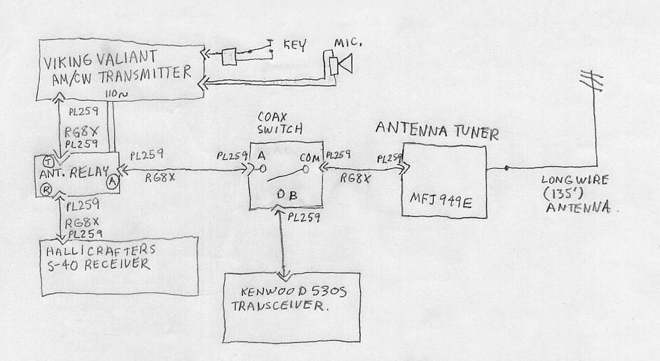
- Multiple RG8X coaxial "jumper cables" to accommodate the antenna relay for the
Viking Valiant transmitter and Hallicrafters receiver, and to allow the AM station to
be located on other side of the shack (possibly*) from the SSB (Kenwood TS-530S) HF transceiver.
- *May need to build shelves for the Viking (transmitter) and Hallicrafters
(receiver) so that they can be located near the other equipment and the common
ground point.
- Switch (with SO-239 connectors) to toggle between the SSB (Kenwood) rig and the AM (Viking) rig.
- Price comparison: It would cost $39.30 to buy (and "D.I.Y.") 32.5' of RG8X coaxial cable and ten (10) PL-259 connectors.
- Price comparison: It would cost $39.90 to buy six (6) pre-fabricated RG8X coaxial jumper cables from vendor [(5) 18" cables, (1) 25' cable = 32.5'] with PL-259 connectors soldered on each end.
|
| Part |
Description |
Vendor (Part number) |
Price ($) |
Quantity |
Date |
Total ($) |
| Microphone Jack |
2-pin, male, chassis mount (for Johnson "Viking Valiant") |
UR (2793) This part was incorrect. The actual 2-pin plug is an (Amphenol 80-MC2M, 2-pin male) |
2.99 |
1 |
17-dec-2007 |
2.99 |
| Microphone Jack |
4-pin, male (adapt to Kenwood "TS-530S" mic. cable) |
UR (2398) This part was incorrect. Wanted the shell, but this was the chassis mount |
2.89 |
1 |
17-dec-2007 |
2.89 |
| Microphone Cable |
2-conductor, shielded ("Heil" brand: Two 18 gauge audio leads residing in a 100% silver braided shield) |
UR (2645) |
1.00/foot |
20' roll |
17-dec-2007 |
19.95 |
| Switch |
2-position, 500 MHz, with SO-239 connectors (Alpha-Delta "2B") |
UR (4787) |
56.95 |
1 |
17-dec-2007 |
56.95 |
| Coaxial cable (RG8X) |
jumper cable, 18" with PL-259 connectors soldered at each end |
UR (2578) |
4.99 |
5 |
17-dec-2007 |
24.95 |
| Coaxial cable (RG8X) |
jumper cable, 25' with PL-259 connectors soldered at each end |
UR (0539) |
14.95 |
1 |
17-dec-2007 |
14.95 |
| Shipping & Handling |
17-dec-2007 |
9.95 |
| Total |
17-dec-2007 |
132.63 |
Table 3 (Part II)
More Parts Needed for Separate AM Transmitter and Receiver
Compiled: 04-jan-2008. Placed order: 04-jan-2008.
Vendor 4 (for reference): UR (Universal Radio) - www.universal-radio.com
|
Overview:
- Additional (longer) RG8X coaxial "jumper cables" to accommodate the antenna relay for the
Viking Valiant transmitter and Hallicrafters receiver, and to allow the AM station to
be located on other side of the shack (possibly*) from the SSB (Kenwood TS-530S) HF transceiver.
|
| Part |
Description |
Vendor (Part number) |
Price ($) |
Quantity |
Date |
Total ($) |
| Coaxial cable (RG8X) |
jumper cable, 36" (3') with PL-259 connectors soldered at each end |
UR (2580). (Astatic A8X3) |
6.49 |
3 |
04-jan-2008 |
19.47 |
| Shipping & Handling |
04-jan-2008 |
4.95 |
| Total |
16-jan-2008 |
24.42 |
|
Overview:
|
| Part |
Description |
Vendor (Part number) |
Price ($) |
Quantity |
Date |
Total ($) |
| N/A |
Type FT-243 crystal (3.837 MHz) |
Brian Carling (AF4K/SK) |
12.00 |
1 |
15-jan-2008 |
12.00 |
| Shipping & Handling |
15-jan-2008 |
5.00 |
| Insurance and Priority Mail |
15-jan-2008 (arrived 22-jan-2008) |
4.00 |
| Paypal Offset Fee |
15-jan-2008 |
1.00 |
| Total |
15-jan-2008 |
22.00 |
Repair History, Continued...
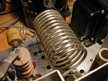
December 7, 2007 (Friday):
Ordered a 5 oz. can of "Nevr-Dull" [sic] "Magic
Wadding Polish" from www.amazon.com. This enabled me to clean the tarnished silver tank
coils (L13A and L13B). Price was $2.82 plus $6.27 freight for a total of $9.09. Arrived
on December 12. The tank coils looked much brighter afterwards, you'll agree.
December 16, 2007 (Sunday):
Used a product called, "Goddard's Silver Dip" (10 oz. jar)
to clean up the numerous silver switch contacts. Used in conjunction with generic (Q-tip type)
cotton swabs on each individual switch. The Goddard's Silver Dip was purchased at
Wegmans grocery store.
Took inventory of the electrolytic capacitors I needed to replace.
(See Table 2).
December 17, 2007 (Monday):
Placed order with Universal-Radio for pre-fabricated RG8X coax "jumper cables", microphone
connectors, and microphone cable (See Table 3). Picked up replacement
capacitors (See Table 2) from Radio Daze.
December 30, 2007 (Sunday):
Replaced electrolytic and paper capacitors: C89, C91, C92, C92A, C92B, C98A, C98B, C99.
For detail, see Table 2.
December 31, 2007 (Monday):
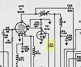
Resistor R3 (a.k.a. the "Chernobyl" resistor) tends to overheat, so it was replaced
as a precaution.
Replace resistor R3 (18k Ω, 2 watt, carbon) with a 18k, 5 watt, 5%
wire-wound resistor. This was a precaution because R3 is known to overheat. Due to its location, it may be necessary
to clip it out and drill holes through the chassis to relocate it on a terminal strip
(a modification) on the other side of the chassis. This would keep it away from other
things that can melt. The R3 resistor is located inside the VFO compartment. It goes to
the voltage regulator tube (OA2 - V2) next to the VFO tube (6AU6 - V1) and is accessible
by removing the plate on the left side of the VFO compartment. This is part of the screen
voltage regulation for the VFO screen. Note that the theory about moving resistor R3
outside the VFO box to keep things from overheating may be a misnomer. The heat from the
R3 resistor may also help to stabilize the VFO when everything is warmed up. The metal VFO box
was provided for a reason, and it may have been to create an oven effect. However; I am
not sure about it at this point.

Put radio back together, re-assemble VFO box, replace vacuum tubes in sockets.
Attach dummy load (Cantenna) and solder leads to the antenna relay. Apply power from
variable transformer. No smoke. Plug antenna relay into socket on back of radio
and test. The antenna switching relay was good. Later experienced a problem with
the antenna relay (a.k.a. "T/R switch") whereby the relay contacts would
not release when the PTT switch was released. Need to investigate or get a new
T/R switch.
Needed a Type 6S6 pilot lamp (120V,
screw base). Lamp is used when transmitting - through the red lens to the right
of the VFO. Needed three Type 51 pilot lamps
(bayonet base). One Type 51 lamp is for the green power lamp, and the other two
are for the VFO tuning dial.
January 2, 2008 (Wednesday):
Purchased two spare Type 6S6 bulbs (lamps) for "transmit mode" at Glenwood Sales.
Picked up a package of ten Type 51 bulbs (lamps) for "power on" and VFO dial at
Radio Daze.
January 4, 2008 (Friday):
Bought an Astatic D-104 microphone for $20. Schematic was included. Base plate cover missing.
Otherwise in decent shape. Tested it, and it worked fine (got modulation).
January 5, 2008 (Saturday):
Soldered 2-pin connector onto D-104 microphone cable. The 2-pin connector is an
Amphenol Type 80-MC2M.
Began following the tune-up procedure as described in the Viking Valiant Operating Manual.
Tuned the pi-network into a 50 Ω dummy load (Heathkit "Cantenna"). All bands tuned up
well except for 160 and 80 meters. There was no grid current on these bands. Brought radio
back up to the shack and ran the coaxial cable and ground wire to it. Continued with the
tuning process. The band switch internal cam (D2) may be out of alignment. I was also not
able to "zero beat" any signals on the "presumed" bands. This could be due to the band switch
alignment issue. Needed a frequency counter to verify.
January 8, 2008 (Tuesday):
Used my Kenwood TS-530S transceiver as a "digital frequency counter." Turned the Valiant up
on its end, and switched it on. Set the band switch to 40 meters (was able to tune that band
earlier) and set Valiant's VFO vernier dial to the low end of the band (near 7 MHz). Turned on the
Kenwood, and listened to the low end of 40 meters. Was able to hear the zero beat signal on all
bands except 80 and 160. Something was still wrong with those bands.
Compared my band switch cam block settings with photos from another Viking Valiant. Verified
that my cam block is set up correctly. See photos of the cam block position on each band
switch setting.
January 9, 2008 (Wednesday):
Removed the VFO box again and began looking for evidence of something which might
have caused the VFO not to oscillate on the 80 m and 160 m bands. Used compressed air,
vacuum cleaner, DeoxIT contact cleaner,
some probing tools (needle-nose pliers, dentist type implements). Was able to separate
a couple of wires that looked close to each other, applied the DeoxIT on the tube
sockets of the VFO tubes, and the contacts of the band switch wafers. I wanted to
identify something specific, but nothing appeared to be obviously wrong. Whatever
I did, the problem was resolved. Was then able to see ample grid current on the
80 and 160 meter bands. It tuned up nicely into a 50 Ω dummy load on all bands.
January 10, 2008 (Thursday):
Made the first QSO with the rig. Talked to Ray
(KC2OHL) on 3.837 MHz. He
said it sounded good.
January 11, 2008 (Friday) 18:00 - 18:45:
Had an extended testing QSO with Dave (KA2J).
He said the audio was real good, and that audio modifications are probably not needed
for this particular Valiant. I varied the CLIPPING dial settings and he said that full
clockwise sounded the best, but the ten o'clock position (3 on the dial) sounded as if
there was more "power" to the audio. Left it in the full clockwise position.
Became aware of a vibration during transmit. Sounded like something loose
inside a tube, but I was not sure. This was verified as normal "talkback" from
the transformer, and does not indicate any trouble.
Noticed that the T/R switch was not always releasing after I let up on the
PTT. Also, had to switch the receiver (Hallicrafters
S-40) into stand-by mode in order to prevent massive amounts of audio feedback
during transmit on the Valiant. This is standard practice with many operators of
older AM equipment. It can be eliminated by using a T/R switch with another set of
contacts that would need to be wired into the receiver's audio circuit such that
when the operator is transmitting, the T/R switch would disable the receiver's audio.
January 12, 2008 (Saturday) 10:00 - 14:00:
Performed an operational set up, and calibration per the Operating Manual with Dave
(KA2J). Dave brought his frequency
counter, and vintage watt meter (TS-1771/U made by Electro Impulse Laboratories under
contract by the Navy Bureau of Ships).
- Bias adjustment. Final amplifier. Adjust Clamper R13. Set R62 for -70 V
amplifier grid voltage. Measure from either end of L7 and ground (chassis).
L7 is under chassis (see layout photo in manual). Set chassis on end to
perform measurement.
- Set static modulation current. Load transmitter to 8 mA grid drive, 330 mA
plate current. Turn meter switch to MOD position. Adjust R61 to 60 mA
(operating conditions are 50 - 70 mA).
- Clamper - R13 (pot near rear of chassis next to clamper tube V8 (6AQ5).
Adjust by checking plate current when turning SW8 (MAN / PTT) switch to MAN
position. Turn SW8 back to PTT position, and then adjust R13 ccw until 10 mA
static plate current is achieved.
- Neutralization: Tune up on 20 meters to 250 mA. Note Final dial setting.
Turn meter to grid position. De-tune final slightly in direction that causes
grid current to increase. Completed when de-tuning causes little or no change
or grid current falls off. There was not reason to adjust this, as it was set
up fine.
- VFO calibration. Use adjustment taps on top of VFO box. Adjusted all bands:
160, 80, 40, 20, 15, 10, 11 meters.
- Load Valiant on 160, 80, 40, 20, 15, 10, 11 meters.
Later in the afternoon, I worked on the T/R switch. Removed the silver end-cap and
cleaned the relay contacts with DeoxIT contact cleaner.
Also lubricated the pivot point of the actuating bar with light oil (the oil
was designed for model trains). the T/R switch performed with 100% reliability
afterwards.
Made a patch cable for the T/R switch (antenna relay) to receiver. The Hallicrafters
S-40 receiver has screw terminals for the antenna connections. Patch cable consisted
of: PL-259 to coaxial cable (2 feet). Both center conductor and shield uses a spade lug.
The center conductor lug goes to the separate antenna screw terminal on S-40. the shield
lug goes to double-screw (jumpered) terminals on S-40.
January 13, 2008 (Sunday) 16:00 - 17:30
Checked into the Antique Wireless Association (AWA) Sunday afternoon AM Net on
3.837 MHz. Signal reports were all favorable. Bob
(W2ICQ) in Syracuse (75 miles
away) reported a "25 over S9" signal. Used the D-104 microphone and
the Hallicrafters S-40 receiver. Antenna was a 113' (34 meter) #14 AWG solid copper
enameled random wire up about 15' (5 meters). I was told that the radio does not need any
audio modifications, and sounds good in stock condition.
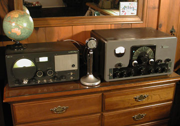
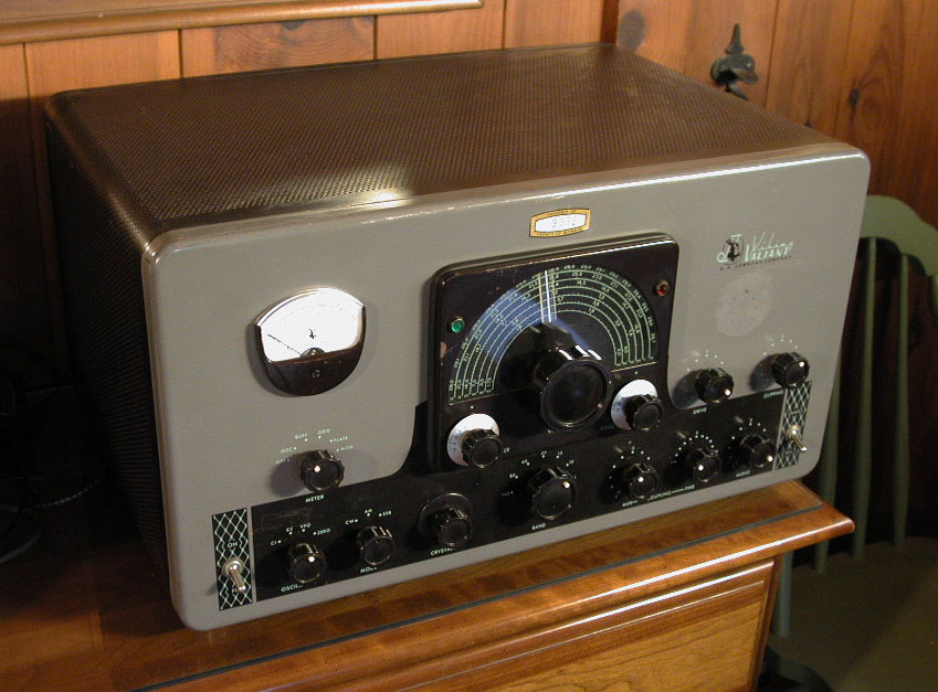
N2AWA / AM station / January 14, 2008
1946 Hallicrafters S-40 Receiver (left), Astatic D-104
microphone (with amplifier bypassed),
1955-1962 Viking Valiant AM transmitter (right).
Distorted Audio Saga
December 28, 2008 (Sunday) 15:30 - 16:15
I checked into the Antique Wireless Association (AWA) Sunday afternoon AM "Pre Net" (as usual)
on 3.837 MHz and received several reports of distorted audio on my signal peaks. I began
checking the basics, and discovered some AC line voltage on the chassis ground stud!
Depending on how the power plug (original two-conductor style) was positioned in the wall outlet,
I measured either 31 v AC, or 61 v AC on the chassis. This explained those friendly little
zaps I was getting when I touched the cabinet.
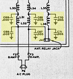
To (hopefully) fix the problem, I replaced the six "low"-voltage-coil
bypass capacitors
(C65, C66, C67, C69, C70, C71) where the AC line comes into the transmitter. They were all tied to ground
(see schematic detail, directly above). If one (or more) of those ceramic capacitors was leaky,
it could explain why there was some AC line voltage on the chassis.
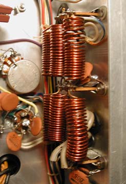
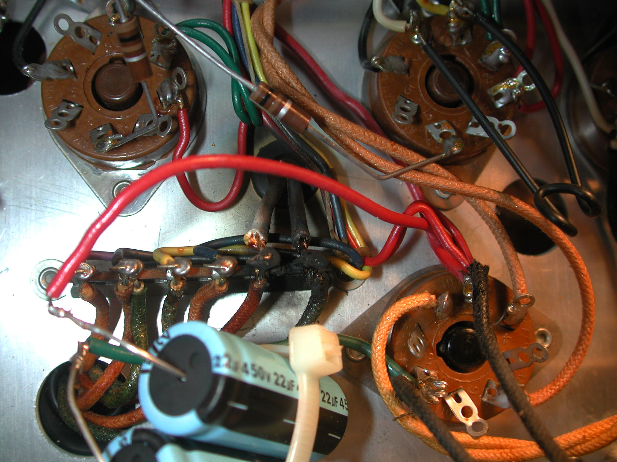
January 1, 2009 (Thursday):
Photo (left): Original, unmolested configuration. The low voltage coils with the old ceramic disk
bypass capacitors on terminal strips, screwed to the chassis. Photo (right): Unsoldered the
coils to gain access to the (2) terminal strips.
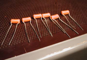
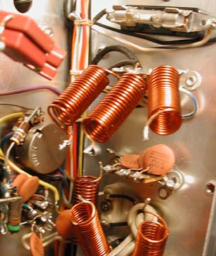
New "orange drop" polypropylene capacitors (0.0047 µF, 600
v)
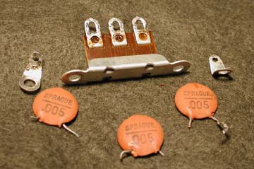
Three of the old ceramic disk bypass capacitors (0.005 µF, 600 v) and
one of the terminal strips. There were two of these configurations hidden behind the coils (see
photo, above).
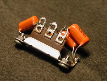
Same old terminal strip with the new capacitors soldered into
place. Did this make any difference? I measured 20 Vac on the chassis after
replacing the capacitors, so that was better than what I measured before,
still not perfect. Not sure where the 20 volts could still be coming from, unless one of the new caps
was leaking, which was unlikely.
An Excuse To Buy A New Antenna
Unfortunately, none of this
horse hockey explains
the "distorted audio" reports I was getting. So to that end, I ordered a full sized (no coils) Hy-Power
80 meter dipole
antenna. The existing end-fed, random long wire antenna was difficult to tune on 3.837 MHz and I could not
fully load the wire with the Valiant without getting some arcing inside the MFJ-949E antenna tuner.
That arcing is what caused the distortion. Description of the new 80 meter dipole: Full-sized (no coils), full power dipole. Features
#12 AWG UV insulated wire, uses stainless steel electrical hardware, an SO-239 center insulator,
and two end insulators. The antenna was completely assembled and ready to install. Just added
coaxial cable and nylon rope. Antenna length: 42 meters (138 feet).
January 5, 2009 (Monday):
The Hy-Power
80 meter dipole antenna arrived.
|
Table 4 (part I)
80 meter Dipole Antenna and Replacement Parts for E.F. Johnson Viking Valiant
Compiled: 30-dec-2008.
Vendor 1 (for reference): RD (Radio Daze) - www.radiosupply.com
Vendor 2 (for reference): UR (Universal Radio) - www.universal-radio.com
|
| Schematic part number |
Value (original) |
Original component and composition |
Value (replacement)
|
Composition of new part |
Vendor (Part number) |
Price ($) |
Quantity (actual) |
Purchased / Ordered |
Date |
Total ($) |
| N/A |
N/A |
N/A |
antenna rope. |
double braided polyester, 1/8", 100', 420 lbs. break. |
UR (2624) |
$11.95 + $4.95 shipping |
N/A |
1 (100 foot) roll |
03-dec-2008 |
$16.90 |
| N/A |
N/A |
N/A |
75/80 meter dipole antenna. Length: 42 meters (138 feet). |
#12 AWG, UV insulated wire, with stainless steel electrical hardware, SO-239 type center insulator, and two end insulators. |
UR (1292) Hy Power (FSDP 80) |
$48.95 + $4.95 shipping |
N/A |
1 |
29-dec-2008 |
$53.90 |
| C65, C66, C67, C69, C70, C71 |
0.005 µF, 600 v |
ceramic capacitor |
0.0047 µF, 600 v |
"orange drop" (type 715P) polypropylene film capacitor |
RD (C-OD15.0047-600) |
$0.54 |
6 |
8 |
30-dec-2008 |
$4.32+$0.31 tax=$4.63 |
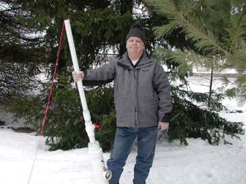
Lynn (W2BSN) visits with his home-brew
air cannon to help install the 80 meter dipole antenna.
February 7, 2009 (Saturday)
Erect 80 meter dipole antenna. "Hy Power" model FSDP 80 (#12 AWG UV insulated
wire). Total antenna length:
138 feet. Handles 1,500 watts.
Lynn brought his home-brew, compressed-air cannon to get the
ropes up into the trees. He used light-weight, pink string (for maximum
visibility) with a weighted projectile (wooden dowel encased in a metal
sleeve) at the end. This served as the feed line for the antenna rope, which
is heavier. We spent about four hours on Saturday. I went
back out on Sunday (February 8, 2009) to take down the old long wire antenna
and re-purpose the antenna rope (from the long wire) to the center insulator
and south end of the 80 meter dipole insulator. Also ran the coax feed-line up
under the eves, behind the gutter. I was out there for another three hours
Sunday. It took a total of 11 man-hours to complete the work. Signal reports on the Sunday afternoon AWA AM Net
(3.837 MHz / 1600 local time) were favorable. The signal strength was
reported to be much stronger than with the random, end-fed, long wire. The new
80 meter dipole antenna also helped the 1946
Hallicrafters S-40 receiver.
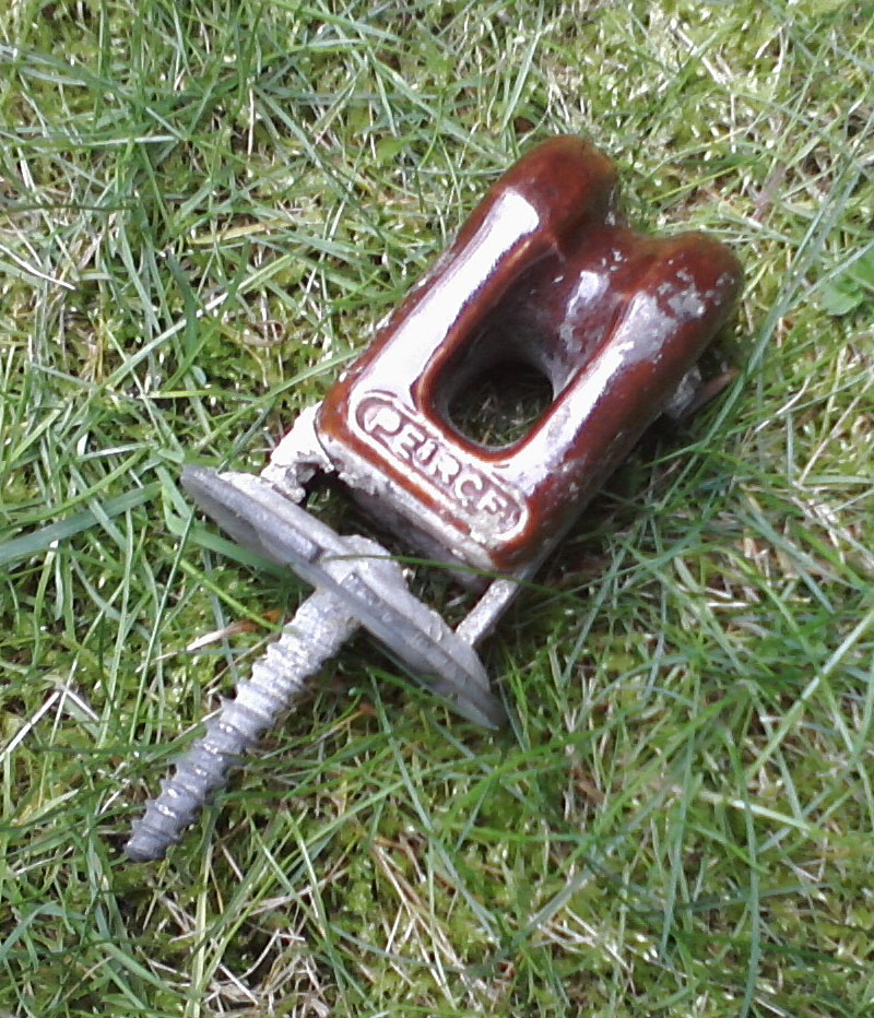
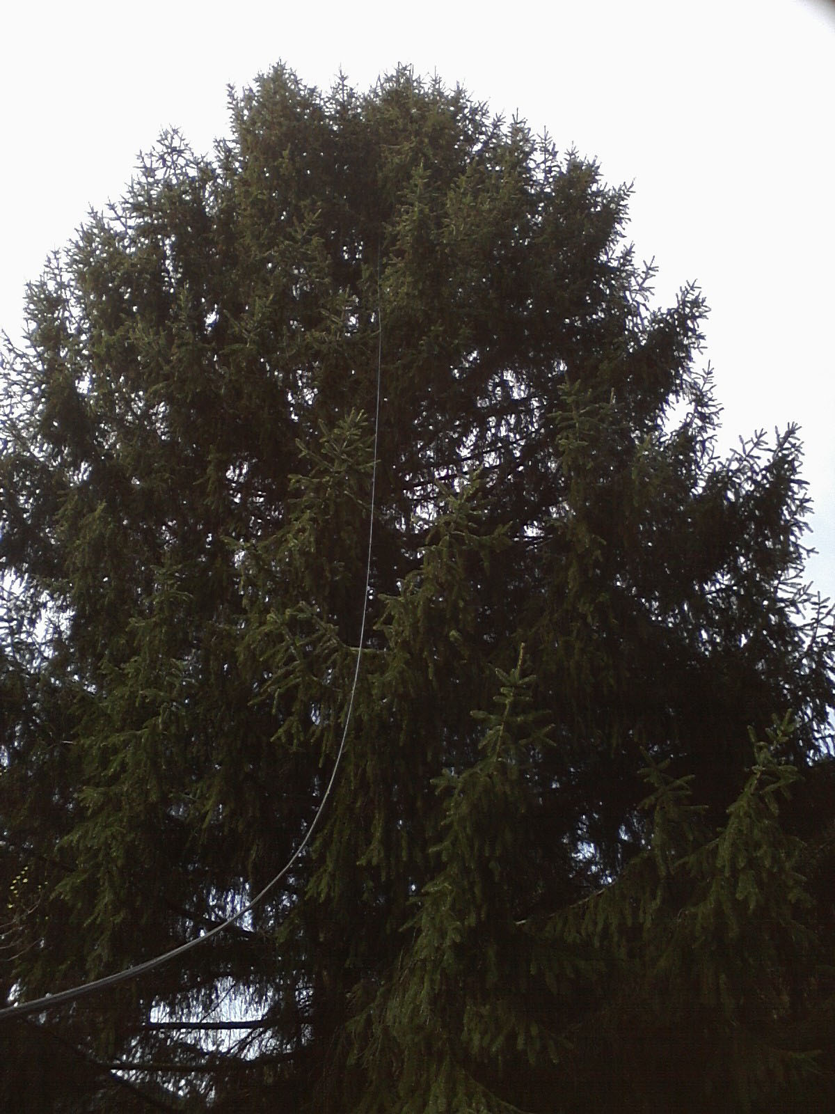
April 14, 2012 (Saturday)
After the Newark Hamfest, Kevin (WB2QMY)
helped fix my "drooping" 80
meter dipole antenna by climbing the
40 foot pine tree* and running new rope through a vintage
ceramic
insulator. A cordless drill made a pilot hole for the
insulator. The main cause of the droop was that the counter-weight (a plastic milk jug filled with sand)
disintegrated and broke free, creating about five
feet of slack in the system. To make matters worse, the original polyester
rope was stuck in the top of the tree, preventing that end of the
antenna from being lowered, as originally designed. *Kevin was more than half
way up the
tree in this photo,
but invisible — a truly majestic tree.
November 1, 2013 (Friday)
The antenna saga
continued...with high winds snapping the rope. On Saturday November 2, I climbed the tree
in the rain, and dropped new rope on both
sides, and hoisted the system back into place. Was unable to locate the ceramic insulator that was installed on April 14, 2012.
Also noticed the clear insulation was peeling off the #12 AWG wire.
Low Modulation Problem
AMfone Forum: My "low modulation" problem
August 5, 2013
Smelled a burning odor while transmitting on the AWA AM Net (7:00 p.m. / 3.840 MHz), so everything was shut down quickly.
At that point, it was not clear if the receiver (1946 Hallicrafters S-40) or the transmitter was the culprit.
After the dust settled, I tuned-up the Valiant and ran some tests, and everything seemed fine (there was modulation, the
finals would load, and the plate current was dipped).
Bob (W2ICQ)
said one of the loading capacitors in the pi-network may have failed because they are
known weak points. He suggested replacing them with "military" mica capacitors (presumably
to withstand higher temperatures, etc.). The manual says the fixed caps in the pi-network are mica,
but I presume not military grade. The pi-network loading circuit is shown at the top right of the
schematic. As the "Aux Coupling" and "Fine Tune" knobs are turned clockwise, the capacitance is reduced,
thus loading (coupling) the transmitter to the load for full rated power input. The modulation issue
did not seem to be tied to the loading caps, but the weakness of these original caps was good knowledge
for future reference.
I made two AM contacts who said my audio was low. I was getting raspy sounds from
the modulation transformer plates, and noticed the modulation meter swinging a great deal. After
backing WAY OFF on the AUDIO pot, the raspy sound ceased and the modulation meter was more normal,
but the other stations could not hear me well. Then everything was shut down again.
The transmitter was able to be loaded and I could dip the plate current, so the RF side of the
radio seemed to be working. The modulation side needed help. Perhaps a plate resistor on one or both
of the 6146 modulation tubes was toasted (this happened before - see "November 11, 2007" on this page).
Not a lot in the way of capacitors in the area, so not sure how a resistor could get fried (by a shorted cap),
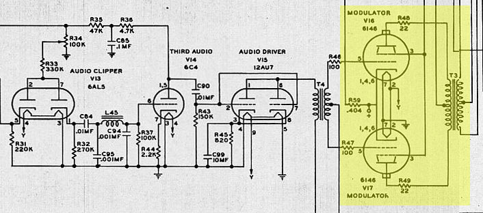
but it provided a place to start looking. The modulation "chain" is shown along the bottom of the schematic.
August 6, 2013
Got the transmitter down into the workshop for further analysis.
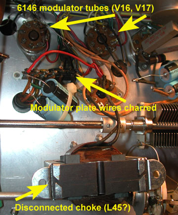
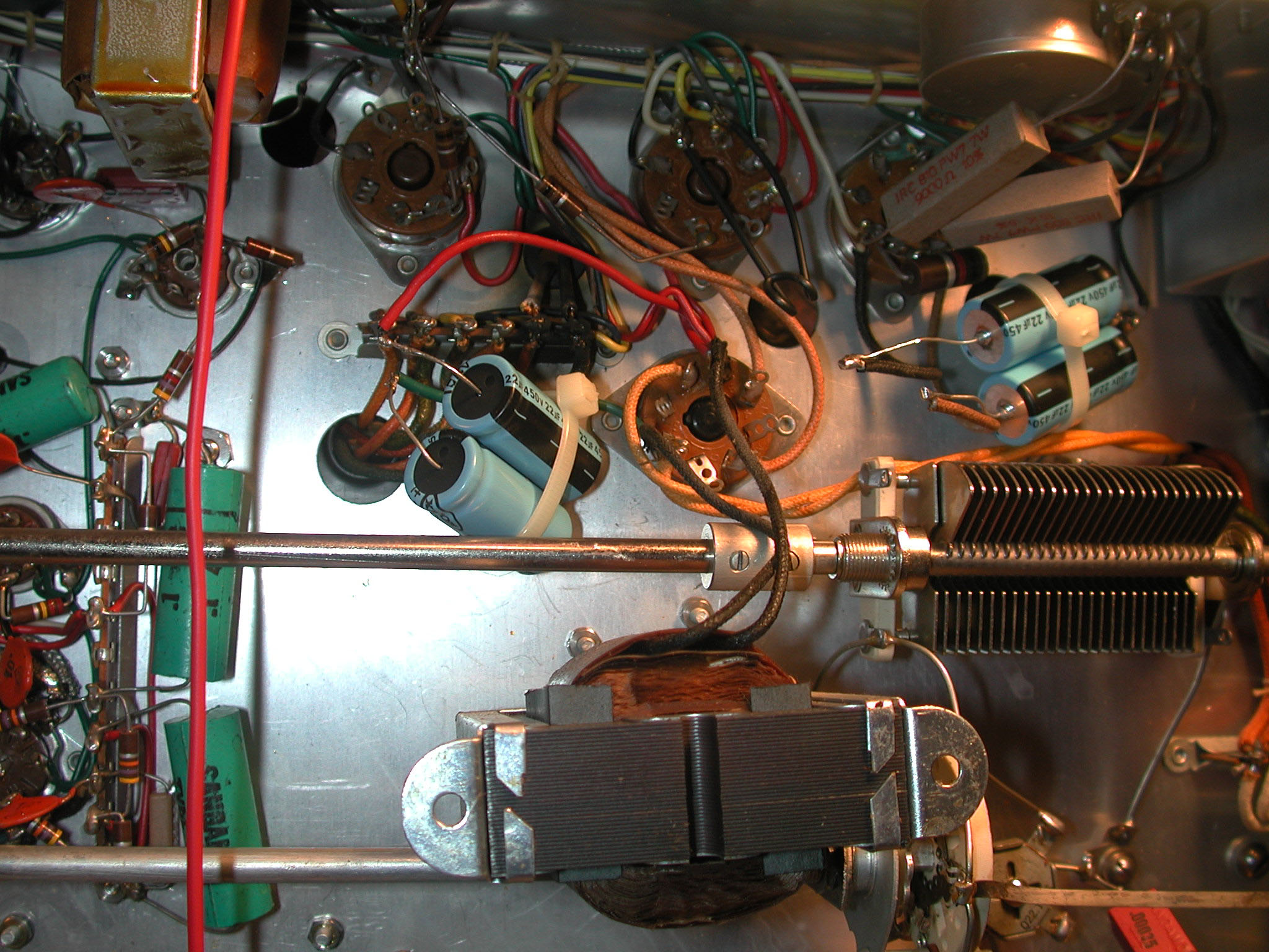
Discovered charred plate resistor wires under the chassis. The inductor (choke) was removed to gain access.
In principle, a choke (a.k.a. inductor) blocks high frequency AC and passes DC
current.
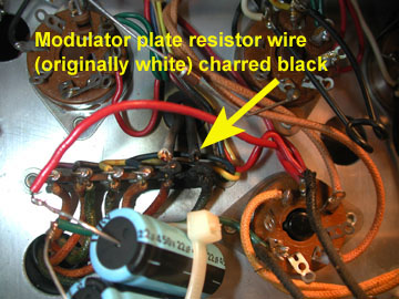
Detail of charred modulator plate resistor wire (on right).
L45 (choke / inductor) was removed to view damaged area.
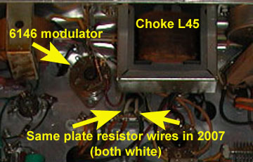
Comparison Photo: Modulator plate wires in 2007. They were both
still white!
The wires shown in the photo are the
modulator tube wires that lead to the modulator transformer T3. Removed the 22 Ω
plate resistors
(affixed with metal cap on modulator tubes), and measured the exact same resistance
from each plate resistor to ground on each side of the modulation transformer primary, so
the transformer looked good.
August 7, 2013
Bob (W2ICQ) saw the photos and said it simply looked like the
phenolic terminal strip broke down. There are six terminals on the
strip, and replacements are available at Antique Electronic Supply (www.tubesandmore.com).
Terminal Strip / 6 lug / 0 common / horizontal
www.tubesandmore.com/products/P-0600H
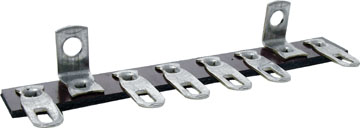
Antique Electronic Supply p/n: P-0600H
Price $4.00 / August 2013
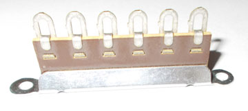
Original (NOS) phenolic terminal strip / Courtesy: Bob (W2ICQ)
Fortunately, Bob had one in his stash and popped it into the mail.
August 15, 2013
- Drilled out the rivets of the original terminal strip.
- Secured the NOS terminal strip with nuts, bolts, and washers.
- Snipped the metal terminal posts off the old strip (with the wires still soldered to them).
- "Tack-soldered" the wires to the new terminal strip posts (eliminates dealing with old, possibly brittle wires).
- Tuned and loaded the transmitter into a dummy load (Cantenna).
- Checked modulation with D-104 microphone (modulation looked good on the meter).
- Put it back into the cabinet.
Thanks to Tim (WB2PAY) for
helping on this repair. The technique of snipping the terminal posts (with the wires attached – and
tack-soldering them to the new terminal strip) came from his television repair days. I was skeptical
at first, but it turned out to be a tidy, effective solution. One of the terminal strip rivets needed
more work being drilled out, so I used a Dremel grinding tool, and a prick punch to tap it out. Vacuumed
the metal and debris multiple times before loading it into the Cantenna.
August 18, 2013 (Sunday)
Checked into the Antique Wireless Association (AWA) Sunday AM Net at 7:00 p.m. on 3.840 MHz (summer time
and frequency). Signal reports were all favorable.
Valiant Knob Pointer Replacements (⅛" diameter x ¼" length)
- Valiant (and Ranger) knob pointer replacements: McMaster-Carr part 97155A413, Plastic Dowel Pin (⅛" diameter, ¼" length), Acetal (Pack of 50 for $3.11 / 18-aug-2013)
Still To Do
- Fabricate "patch cable" for existing microphone. Four pin
connector on one end and two-pin (Amphenol 80-MC2M) connector on the other
end. See Table 3.
Footnotes
1 Charles "Chuck" Brelsford (K2WW) was an early
Antique Wireless Association (AWA) member along with Bruce Kelley
(W2ICE), Lincoln "Linc" Cundall (W2LC), Ken Gardner (W2BGN) and Robert Morris
(W2LV)
Acknowledgements
Many thanks to Lynn (W2BSN)
for the power plug for antenna relay (HC6 crystal case), antenna relay, two-pin connector
(Amphenol 80-MC2M) for microphone patch cable.
Bob (W2ICQ) for the mode knob with
white "dot" (pointer) insert, email advice and support.
Chuck (K1TLI)
for the advice on the band switch retaining ring.
Dave (KA2J)
for photos of his Viking Valiant band switch settings and help with the operational calibration.
Bob (W2ICQ) for the NOS terminal strip
on the low modulation problem.
Tim (WB2PAY) for technique and assistance
with tack-soldering old wires to new terminal strip.

c o n t a c t / r a d i o w o r l d
E.F. Johnson "Viking Valiant" AM Transmitter
Established: November 4, 2007
Last Update:
November 07, 2022
Links Verified
October 2, 2020
© Black Sparrow Photography / Jeffrey P. Miller (N2AWA)


