Douglas Broome / douglas.broome@verizon.net / March 19, 2009
I. PROBLEM
The heater valve on your Mercedes-Benz Ponton is stuck in the open or closed position. What is the problem? More importantly, what is the solution? WARNING: Do not force anything. Read this article first!
II. DIAGNOSIS
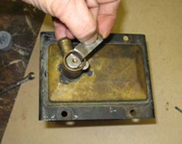
Remove the Bowden cable from the lever on the valve. Do not lose the tiny e-clip. Try to manipulate the lever. Do not force it with pliers or a wrench. If it fails to move easily, the valve assembly is not operating properly or is completely corroded into its position. If it moves easily, the problem is in the Bowden cable, and where it mounts in the dash, or possibly the pivot for the lever fixture in the dash. This article addresses only the valve in the heater radiator.
III. TOOLS
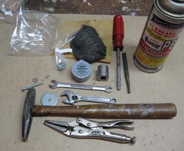
Several of the necessary tools may already be in your kit:
- Light hammer
- Flat-blade screwdriver of appropriate size
- 7 mm open-end wrench, or small adjustable wrench
- Needle-nose locking pliers
- Punch or nail set
- 17 mm socket, or something of comparable diameter
- 4 x 40 mm hex-head screw
- 4 mm nut to fit the hex-head screw
- Fender washer larger than the socket with hole large enough for the screw to pass
- Waterproof grease
- Fine sandpaper and/or 0000-gage steel wool
- Bench vise or human helper
- Dremel type tool with round brass brush
- WD-40 (household water displacing spray)
See Photo 1:
Photo 1.
IV. PARTS
Only one spare part is required. The O-ring on the valve must be replaced. Its diameter is metric, and comparable size O-rings were not available at my local plumbing supply house. Unless you have access to metric plumbing supplies, a new O-ring readily comes from Mercedes-Benz parts sources. Mercedes-Benz part number: 000-835-58-98. They are not prohibitively expensive, being on the order of $6.00 USD. Readers outside the United States may have better luck finding the O-ring at plumbing suppliers. Take the old O-ring to the store to find the equivalent size.
From what I have come to understand, a standard metric O-ring of the following size is appropriate for the valve: inside diameter 12.37 mm and cross section 2.62 mm. Sometime this is referred to as a general O-ring metric number 112.
V. CAUTIONS
There is little to mess up, and little harm you can cause yourself on this job. However, one potential problem is at the beginning of the disassembly process. The slotted screw at the top of the valve may be severely stuck in its threads, and the slot may already be damaged. If you snap the head of the screw off, or really bung up the slot, you are screwed (pun intended). Also, you really do not want to round off the square brass mounting point by forcing the open-close lever.
Another potential problem is snapping off the part of the housing above the slot for the stop lever. Avoid pushing on it. I broke this once, and had to braise it back into place.
Yet another danger is trying to bite off more than you can chew at one time. The turn lever, stop lever, and valve are different on the left side radiator versus the right side radiator. If you mix up these components, you will have an entertaining time figuring out what goes where. For this reason I suggest attacking one radiator at a time.
VI. LABOR
The threshold decision is whether to remove the heater radiators from the car to do the work on the bench. The task can certainly be performed with the radiators still in the car, but mine were removed for other reasons. My opinion is that it is easier on the bench, but not by much.
Removing the Valve
Assume the radiator is out of the car, on the workbench. Fix it gently in a bench vice or have a helper hold it. Be careful of the tube at the bottom, as it is only soldered into place. Therefore, do not press down too hard on the radiator.
Find a flat-blade screwdriver that fits/fills the slot on the screw. If the screw does not turn easily, do not force it. Fit needle nose locking pliers to the sides of the screw head. Lock into place. Then, slowly try to turn the screw, using the screwdriver and the locking pliers together, counterclockwise. Slowly is the watchword. This has worked for me on all eight radiator valves I have done. See Photo 2:
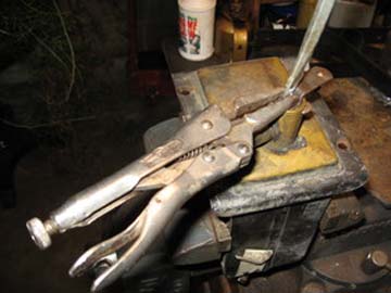
Photo 2.
Put the screw and other parts into a container for reuse. New screws are available in any hardware store although they have either hex heads or Phillips heads, not slotted ones.
Carefully observe the position of the lever with respect to the radiator, and its position with respect to the square mounting point. Take a photo or make careful notes. This will be important at the time of reassembly. See Photo 3:
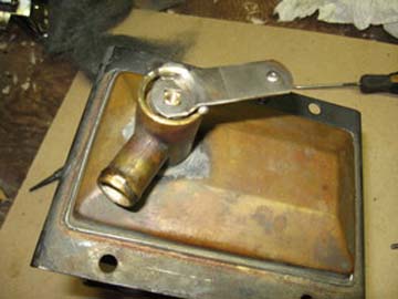
Photo 3.
Observe the stop lever and note its location in relation to the slot in the housing through which it extends. It is probably butted up against one end of the slot or the other. It will not come out at this point. The valve and stop lever must be driven downward into the housing a short distance. Use the hammer and nail set/punch. Tap lightly just until the stop lever comes off the square mounting point and comes out through the slot. Carefully note and record which side of the stop lever faces up. The edges of the tang are not identical, so reinstallation upwards or downwards makes a difference. See Photos 4 and 5:
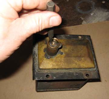
Photo 4.
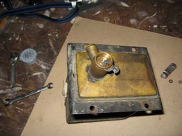
Photo 5.
Now assemble and fit the homemade valve extractor tool. Screw the nut all the way up the threads of the screw. Next, position the fender washer against the nut. Fit the socket, drive-end up, next to the fender washer. Holding everything in place, screw the bottom threads of the screw into the receiving threads inside the square mounting point as far as it will go. You are putting this screw into the hole where the original slotted screw was. Let the socket nestle carefully onto the top of the housing. Tighten the nut by hand clockwise onto the fender washer. The valve is now ready for extraction. See Photo 6:
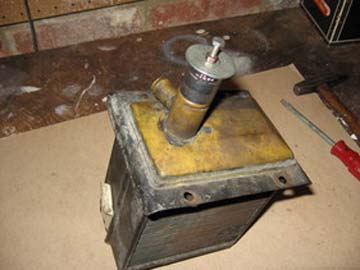
Photo 6.
Fit the 7 mm wrench or adjustable wrench to the nut. Tighten the nut clockwise as far as it will go. Do not over tighten. See Photo 7:
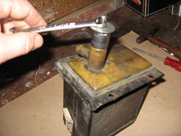
Photo 7.
The valve will come right up. IMPORTANT: Observe and index the position of the hole and slit with respect to their position in the housing as they emerge from the housing. This is essential for correct reassembly.
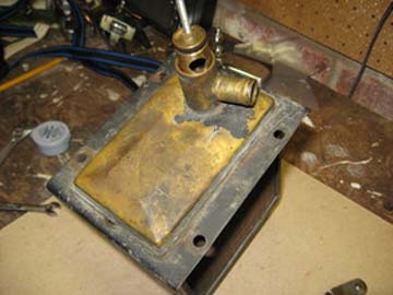
Photo 8.
The next step is to carefully wiggle the valve out of the housing and place it on the bench. See Photo 9:
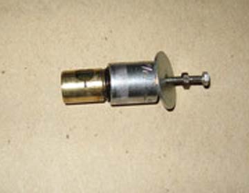
Photo 9.
Remove the extractor assembly. Remove the O-ring.
Cleaning the Valve and Housing
Now the housing and the valve are ready for cleaning. Use the sandpaper and/or steel wool and, with your little finger, ream out the housing as far as possible. With the steel wool use some WD-40 on it. Follow this with the brass brush on the Dremel tool. Moderate speed up and down several times. Clean the valve with steel wool and WD-40. Use the Dremel tool and brass brush to clean out the O-ring groove.
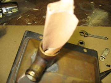
Photo 10.
Refitting the Valve
When everything is clean and shiny, it is time for a test drive. Put the long screw back into the valve. Insert the valve into the housing. It should move up and down and around very easily. Remove the valve. Fit the O-ring. Apply a thin film of waterless grease all around the O-ring and into the groove. If you wish, also put a very thin/light film of the waterless grease on the walls of the housing and on the valve itself. I mean a very light coating. Refit the valve. It should move easily.
Remove the valve one final time. Refit it carefully so that the position of the hole and slit go back into the housing in exactly the same orientation that they came out with respect to the housing. This is VERY IMPORTANT.
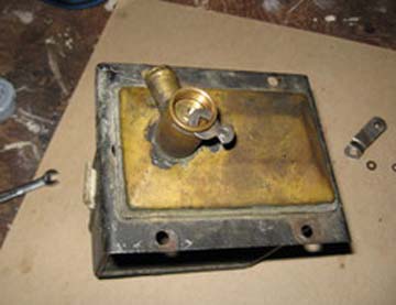
Photo 11.
Push the valve down far enough to be able to refit the stop lever onto the square mounting point through the slot on the housing. Be sure that the original side up, as it came out, is the way it goes back on. Pull up the valve. Refit the turn lever carefully in keeping with its original position with respect to the housing and the square mounting point.
Photo 12.
Re fit the original slotted screw or a replacement.
VII. WHEN YOU ARE DONE
The valve is in its closed position when it more-or-less points forward to the point where the stop lever hits the end of the slot in the housing. In this position, coolant does not flow through the radiator. When the lever is in full open position, it points generally towards the engine. That allows for full flow of coolant.
VII. NEXT
The same job can now be done on the other radiator, and things will go much quicker and easier.
Disclaimer
The usual disclaimers apply. Use the information herein entirely at your own risk.
Acknowledgements
The usual thanks go to Jeff Miller, editor of www.mbzponton.org, for adapting this article for publication.
Created: March 19, 2009 / Jeff Miller
Revision A /
September 18, 2014
© www.mbzponton.org