Anthony Tugwell / AnthonyT@Mail.com / South Australia
Introduction
I am pleased to provide a bit of extra information about my Mercedes-Benz Ponton fuel pump reconditioning, just completed. I have tried specifically to add to the other articles already included on the website (see References), covering points which I was initially puzzled about, things which I feel can usefully add to our knowledge, and some suggestions, clarifications and the like.
- Mercedes-Benz Ponton Fuel Pumps / by Douglas Broome
- Rebuilding Mercedes-Benz Ponton Fuel Pumps / by Ray Ilich
As with all such advice, this is presented as personal experience and might not necessarily cover your own Mercedes-Benz Ponton. As one example, the later W180 series Pontons do not necessarily have a pump with a priming lever.
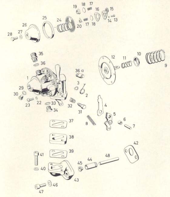
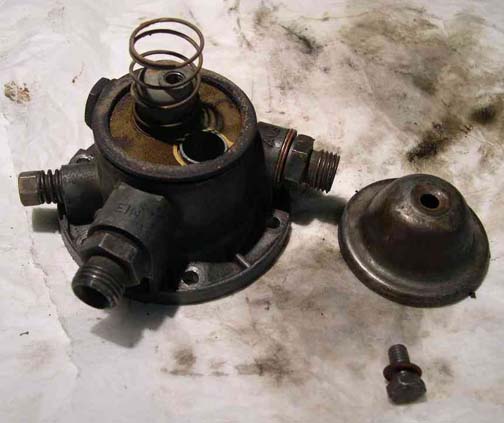
Refer to my photographs while you read this article. Refer also to the illustrated parts diagram which has all items numbered. I use those numbers throughout the text.
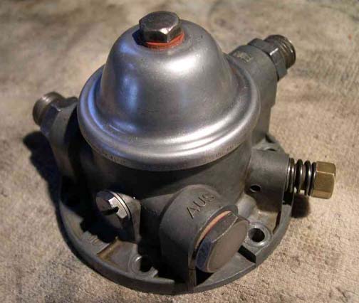
Illustrated parts diagram for Mercedes-Benz Type W180 220S Ponton fuel pump with priming lever
Parts Kit
Doug Broome and others have written at some length about this subject. I was lucky to source a "long" kit from Phil Langlois which I understand was intended for a European UNIMOG. These parts are becoming scarce. Beware also of original equipment which might include "new", but actually unused and therefore old rubber parts, for example the diaphragm.As well as items listed by Doug, my kit included the following (the names are mine):
- Item 10 one valve spring locator
- Item 20 one diaphragm spring locator
- Item 37 (or 39) one gasket (but of a different shape)
I was interested to see that item 15 is made of a hard white PVC, not the aluminum alloy which the original is made from. See photo.
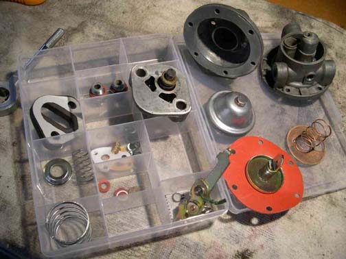
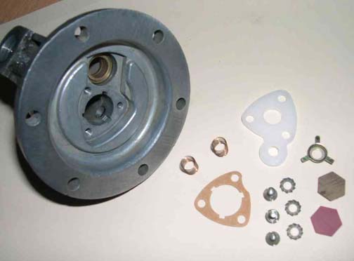
New and reconditioned items prior to re-assembly
Additionally, I needed to order one more gasket from Mercedes-Benz (item 39, or 37) and one gasket (item 42) which fits against the engine.
Disassembly
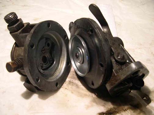
The fuel pump is attached to the front-left side of the engine, down below the distributor, via a right-angled bracket which houses the cam follower. Refer to Doug Broome's article and Håkan Johansson on this cam follower. As Doug says, it is best to remove the pump and bracket together. After disconnecting intake and exit fuel lines, (and plugging them as necessary with a rag or similar), remove the two Allen (hex) head bolts attaching straight into the side of the engine. The pump will come free.
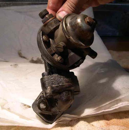
Fuel pump and engine bracket just removed from car
On your bench, remove the engine bracket by undoing the two similar Allen (hex) head bolts attaching to the pump. You will now see the diaphragm operating lever. Refer to photos.
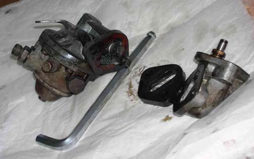
Pump and bracket separated — Note cam follower at top of bracket
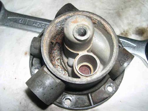
Refer to the Ray Ilich article for disassembly. However you also need to remove the pump cover screw and gasket, take off the cover and carefully remove the copper filter and spring inside. These will be replaced.
Filter cap removed showing original filter and spring inside
With filter removed, a lot of debris is visible
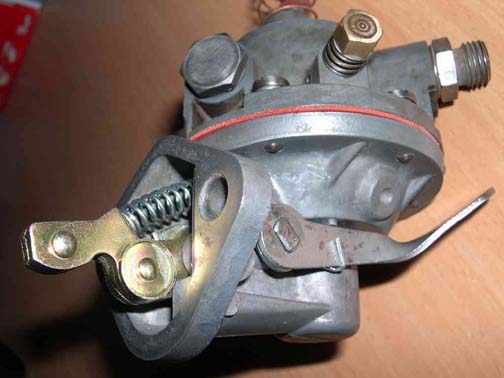
Also not noted, but to be replaced if you have the "long" kit, is the lever assembly and spring, (items 4 to 8, you might need to re-use 7). So remove the existing lever spring plus lever assembly and pivot. You can now take out the priming lever (to be re-used), and its spring and clip, (items 2 & 3).
Pump body separated showing original diaphragm

Original valves seemed to be in fair condition
Clean up everything with a suitable cleaner. I used carburetor cleaner from a spray can which worked quite well. However there are all sorts of little nooks and crannies in and on the main body of the pump which need a bit of work; cotton buds and more carb cleaner should suffice.
The following I would recommend as desirable. They are not strictly necessary but seem sensible where you are rebuilding an item which might have been in service for 50 years.
Carefully tap the threads within the body of the pump. This includes the 6 diaphragm fixings, fuel inlet and outlet, (also blanking piece on mine), brass jet (item 31, 32, water drain plug); thread for cover retaining screw (item 22, 23).
Carefully use a thread die on the above equivalent male items.
Carefully clean up the exteriors, bolt flats and the like of fuel fittings, water drain plug, etc. using fine wet or dry emery paper.
As Doug and Håkan have noted, carefully rub the mating faces of the two halves of the pump with a fine emery paper, on a flat block if you have one. This is where the diaphragm is held.
Because the pump body is made of alloy I saw that corrosion, albeit slight, was evident all over, and it was for this reason that I did the above things. It certainly made reassembly a lot easier and I suspect that all bolts and fixings tightened up far better. You must of course, because the metal is somewhat soft, be careful to not get a thread crossed or over-force a tap or die.
Having cleaned up all parts, I saw that the pump cover, (item 1) was unlikely to buff up to a reasonable appearance. I found a "soft chrome" oil paint and spray-coated it carefully with two coats. The result was good and cosmetically I think it looks pretty correct. Refer to reassembly photos.
Re-assembly
Refer to Ray Ilich's article but bear in mind the extra steps outlined above. Step 8 should include replacing the copper filter and spring, (a bit of care here), also the cover gasket and then replacing the pump cover, which Ray refers to as a bell cover.
New filter and spring in cleaned up housing
Filter and refinished cap in place
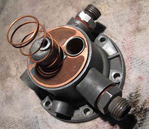
Then as part of Ray's step 8, turn the housing over to replace valves. Refer to my photos.
Note: I actually did the valves first and then the filter, etc. It does not matter which is done first.
New valve parts showing hard white plastic item 15
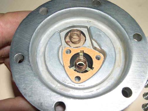
Valve springs, valves and gasket in place
Valves completed
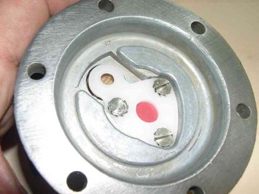
Step 10 is then amended to include replacement with a new lever assembly and lever pivot, (but not spring at this point). The lever pivot is a hand-pressure press fit. It IS a bit of a juggle to get the lever engaged with the diaphragm locating lug but you will get there, as long as you leave the 6 diaphragm bolts loose.
Tighten the 6 bolts carefully and alternating cross-wise in pairs. Check diaphragm movement with the lever. When correct, maneuver the spring (item 8) into position.
This view shows new diaphragm lever (cadmium colour, left) and priming lever extending right
Re-install the priming lever assembly, its new securing circlip and new spring (items 2 & 3). For me this was tricky as the spring is awkward to fit. I do not have any special hints except it might help to try to fit the spring while the lever is slightly out of final position. Then press it home and fit the circlip. Try the priming lever's cam operation against the diaphragm lever. You should hear suction through the valves and fuel inlet/outlet.
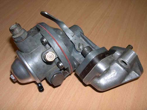
Completed fuel pump
Step 13 should be done on the bench not on the engine. That way you can easily see everything going together and only afterwards attach pump and bracket to the engine.
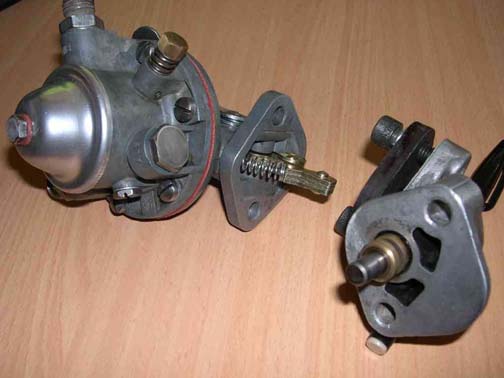
Pump and engine bracket before bolting up
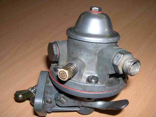
Pump and bracket together and completed
Priming Lever Operation
There is some information on this in the original Instruction Manual for the car. It is on page 32 of Edition A, (including Edition B). In particular there is a description of the occasional situation where your priming lever appears to not operate properly:-"Every time the carburetor or fuel pipes have been emptied, or when the tank has become empty when driving, press down the hand lever on the fuel pump about 10 or 12 times. When doing this a slight resistance must be perceptible and the sound of fuel sucked in and sprayed into the carburetor must be clearly heard; the spraying noise will stop as soon as the carburetor is full.
If no resistance is felt and if no sucking or spraying noise can be heard, which is possible at a certain position of the crankshaft, actuate the starter for a moment, so that the position of the crankshaft is altered and then the hand pump will function."Addendum
I did the above work after the car broke down because of a fuel pump problem. I might say this is the first time my car has ever let me down.In order to get me going and to speed things up I let a local mechanic "fix" it. The pump was full of a lot of accumulated debris and I knew that a reconditioning kit should be used. We made enquiries about a replacement pump by Pierburg and I was very pleased when it seemed to be available. However it turned out to be a "modern" version of the original mechanical one, fully sealed and the like. I said "No."
The mechanic cleaned up the pump to get me going, but I was not happy with the result. It was not fully clean and in particular I discovered that the spring on the priming lever was now broken. So I asked Phil Langlois if he had a reconditioning kit, and luckily, he did. It also turned out to be the "long" version which was good news.
Anthony Tugwell
South Australia
January 2007
Created: January 31, 2007 / Jeff Miller
© www.mbzponton.org