1958 Mercedes-Benz 220S Ponton
Gantry Fabrication, Engine Removal, and More...
Chris Williams / Marion, New York / 1958 Mercedes-Benz Type 220S
Related page: Ponton Engine Removal (I)
Introduction / January 10, 2012
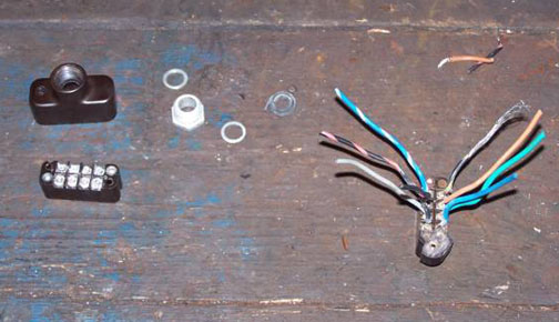
Let's begin with some background on why I started this in the first place. My dad had the engine rebuilt while I was in my undergraduate days. I’m not sure how many miles he actually put on the car since then, but It seems like it’s around maybe 30,000 or so. The real reason for doing this was a failing wiring harness, wherein one of the horns came on all by itself one day, and wouldn’t shut off until I dropped the battery ground on the car. However, as we began to work our way down to the harness in the engine room, removing some pretty deteriorated heater boxes along the way, it became clearer to me that the engine room needed a touch up, and there was peeling paint down along the body rails that needed attention, etc. It seemed like the smartest thing would be to simply remove the engine, check the heater pipes, cores, etc., and do this job right. Also, I’m thinking I may have heard a bottom end knock in the engine the last time it ran – it wasn’t loud, but now’s a chance to get the engine out to my engine shop and have it thoroughly checked – so with the "scope creep" alert sounding loudly in the background, I’m off down that slippery slope that describes every restoration job I’ve done and seen – the problem is that we can’t seem to stop until we get to the bottom of the slope – I’m just not sure how far down the slope actually goes. However, the car deserves it, and I need to make it right now so when I’m through with it someone else, possibly my daughter, can take on the next stewardship role with minimal issues. It’s absolutely past the "in for a penny" stage and we’re about ready to start counting pounds. Seems like a good way for an old guy to entertain himself.
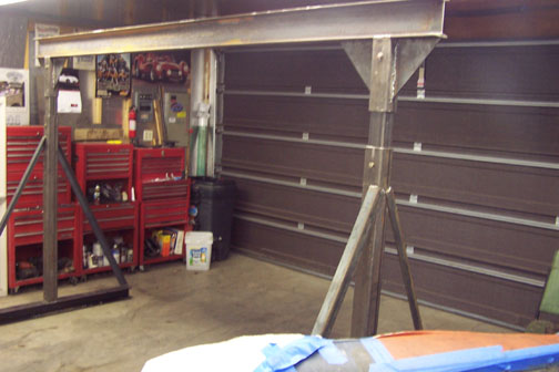
So, the saga continues. Here are some photos of the gantry in assembly and getting loaded into the shop. I had a local fabrication and welding shop get the steel for me, cut it to length and drill the 9/16" holes in the tubing. Then I stuck it together over the weekend and finished the assembly.
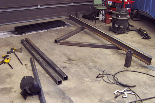
Gantry steel laid out
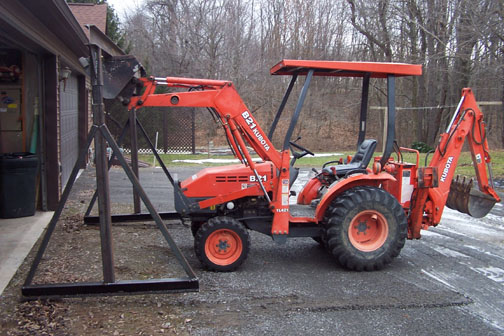
Will it fit in the garage?
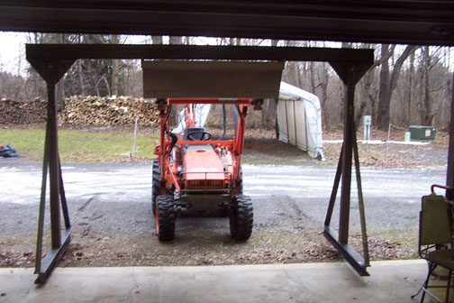
This will be used to lift the front of the car high enough to get the engine and sub-frame out. There’s still a fair amount of work to be done to get ready to actually make the lift, but at least now the gantry is in the shop, out of the weather and ready for final touches.
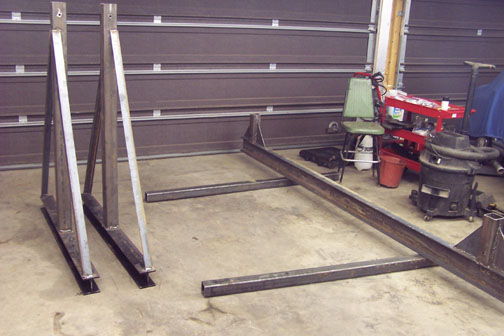
The plan is to use car dollies to actually move it around the shop, and to do that I’m going to build some jacking plates that bolt onto the base beams of the legs (so they’re removable) and some serious wood blocks to distribute the weight on the dollies.
Vince at Shade Tree Engineering provided the gantry plans. So far, so good – now it’s on to (for instance) getting the Hydrak clutch servo off the car and out of the way, as well as all the other stuff that still connects the car to the sub-frame.
Update / February 1, 2012
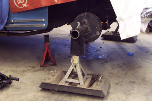
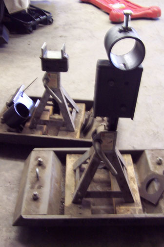
So, the "Great Gantry Exercise" is proceeding apace. The first shot shows some flange plates that I built, attached to a length of 2 ½ inch pipe with a reinforcing gusset, that fit up to my "roller stands" that I’ve been using to elevate the "wire wheel" cars (MG and other British sports cars) while working on them. This is the first undertaking to use wheel studs instead of a wire wheel hub, but the result is I can continue to move the car around in the shop as needed for optimal positioning, yet be able to free up a bay if I need to bring in something else for a running repair.
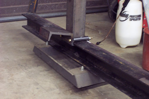
The second shot shows the "jacking plates" that I can bolt onto the gantry and place it, as shown, on a rollmaster dolly on each side in order to move the gantry around in the shop. I elected in the end to not put casters on the gantry, but to use rollmasters instead, since I can more fully distribute the load on the shop floor without casters, and I have no reason to conclude that my shop floor, poured as a garage floor, is anything other than 4,000 psi concrete with some mesh somewhere in there.

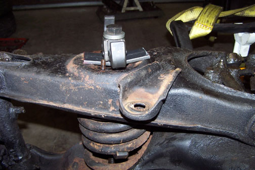
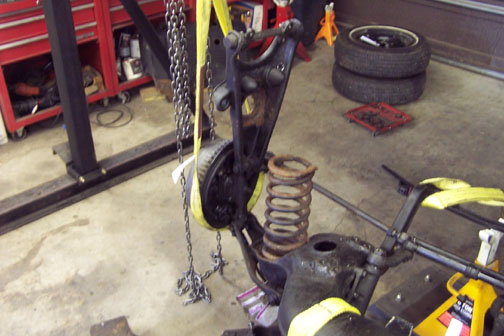
The third shot shows the gantry in position to hoist the back of the car using the jacking sockets. This was necessary to elevate the car onto wheel ramp stands, so I could get under it and remove the exhaust system from the rear (of course) since that was the only readily apparent way to clear the exhaust manifold ports prior to actually lowering the engine out of the car.
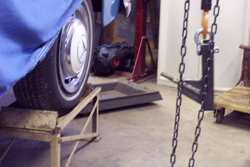
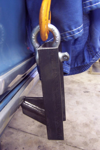
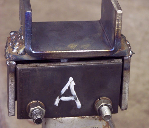
The last shot shows one rear wheel up on the ramp stand, as well as the "pin block" I had made, which fits the jacking sockets and connects to the chain fall on each side using a two-ton anchor shackle. I elected to go with two-ton capacity shackles on a one-ton capacity lifting leg (on each side) simply because the shackles are under quite a bit of shear stress at the pins and I just wanted the "headroom."
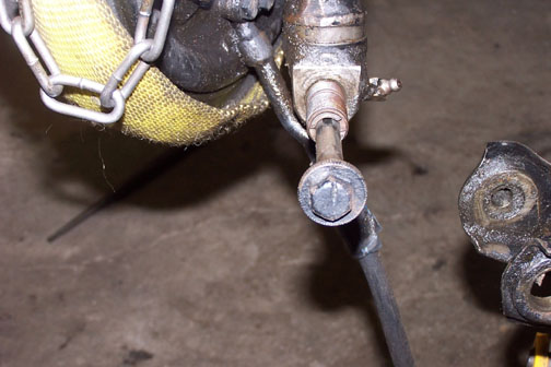
At this point I have one more brake hose to undo and I should be ready to try and get the engine and sub-frame, etc. out of the car. Of course, that brake line connects behind the heat shield that protects it from the front pipe, and presently that heat shield isn’t moving – yet. I promise to document the actual engine removal with photos as it happens.
Update / February 4, 2012
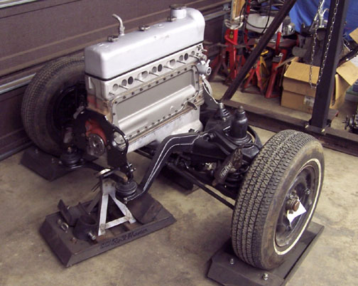
First of all, the engine and sub-frame rolled out "almost" as planned today. The lift pin blocks worked as designed, the gantry was the perfect tool for the lift, and I adapted Bruce Bristow’s design for a tail wheel, which did the job for me. The only thing I forgot was to undo the choke cable where the sheath attaches to the rear carb. Yep, I did disconnect the cable, but I missed disconnecting the sheath. I’ll see if I can collapse the stretched out sheath, but if not I may need a new(er) cable. One thing I did do, which was very helpful, was to put the front wheels on rollmasters. That let me move the engine and sub-frame assembly from side to side, or cock it at an angle as needed. I also put the body back on a variant of the roller platform stands, so with the rear wheels on rollmasters and the front supported on rolling stands I still have the flexibility to move the body around in the shop so as to get it out of the way, or put it in a prime working location as needed.
"Stand Caps"
Here are a few more photos. The first shows the variation in "stand caps" between the earlier design for the wire wheel cars and the newer "crutch" design sized to just fit the frame rails under the car. I have these positioned at the same point as the jacking socket locations at the front, and the doors open and close with no strikes when the car is supported on the rear wheels and the rolling crutch stands.
The second shot shows the engine and sub-frame, etc. mid-way out from under the car.
This also shows the rollmaster platforms under the front wheels.
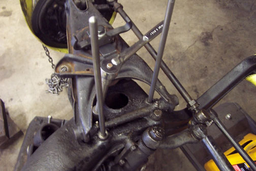
The third shot shows one of the lifting legs connected to the gantry. The critical issue here is ensuring that the lifting leg doesn’t touch the trim or finish as the car is lifted. I used grade 5/8 inch washers to space the pin block out a little farther – three seemed to do it, and the gap shown is the gap under strain (this was taken during a dead hang exercise prior to actually removing the flange plates and putting the front wheels back on in preparation for the lift.
Finally, the last shot is the engine and sub-frame out of the car. I figured this was a good place to stop for the day, but now I’m staged for more work to do.
If it fits, the fifth shot is a close-up of the crutch box fitted to the top of one of the roller stands. This is no more than a section of ¼ inch plate bent to a U, with a flat plate used to clamp it on the top of the stand, and then another U welded to a piece of flat-bar, also welded to the box that clamps onto the stand. The car feels pretty safe sitting on these stands since the weight of the frame rails actually rests on the underside of the top of the clamp box, which then carries the weight down to the rollmaster and on to the casters. Not much to give.
For anyone thinking about using this technique themselves, I can’t emphasize enough the importance of doing static hangs prior to actually doing any lifting. I typically waited about ½ an hour for the static hang to prove itself, and after each static hang I pulled the pin blocks back out of the sockets and checked for any deformation of the pins. This is particularly important when using washers to space the blocks farther away from the car, since it creates a longer section that could bend rather than emphasize shear stresses, and bending is a sign of weakness and thus a "failed test", which should prohibit the car from actually being lifted until the equipment can prove itself strong enough not to bend. Also, in my case it’s serendipitous, since I didn’t actually plan it this way, but when lifting the tendency of the top of the pin block is to roll away from the car rather than towards it – also a healthy approach to mitigating any bending action, which might result in the pin block or the shackle touching the paint or trim.
One other point I should make – with the Triumph, which is a roadster, we found a lot more body flex when lifting the car, particularly when putting it up on ramp stands at both ends, one corner at a time. It was necessary to keep the doors closed when lifting, I felt, to control that flex. With this car, granted it’s a sedan, but nonetheless although the car has a little flex when I start lifting at one jacking socket and then run around to the other chain fall to catch up on that side, this body is SOLID – the word "tank" comes to mind. It’s a real pleasure working on a car so well thought out for servicing, even if the methods are a little unconventional – at least to someone used to working on the English cars. The gantry approach to lifting has also been gratifying. In the back of my mind, I want to, in the future, fabricate some wheel slings that will let me use the gantry to lift one end of a car (both sides) at a time, similar to what I’ve done on this job but for a car that doesn’t have jacking sockets in place. I’ll seek to try that when I get to the MGB and Austin Healey waiting patiently for me in the barn.
More to come...
Chris
Update / February 18, 2012
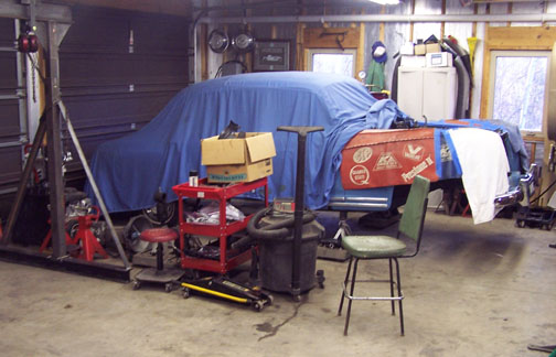
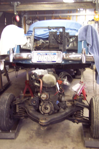
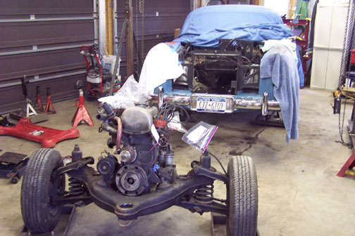
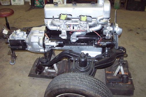
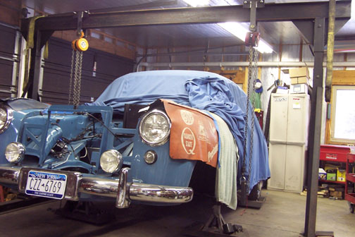
I pulled the engine off the sub-frame this week and broke it down to the point that it’s ready to go out to the engine shop. The first photo shows the car over in the far bay of the shop, where it will likely stay while we get the engine bay cleaned up, painted, etc. Depending on how the engine work goes and what the engine really needs, we may be able to start laying in the new harness before we put the sub-frame back under the car again – but I don’t want to get too far ahead of myself. I should point out that the car remains completely mobile even in this state, so I have the option to swing it out sideways in the shop and clear space on both sides if needed. Strike a blow for roller platforms, to be sure.
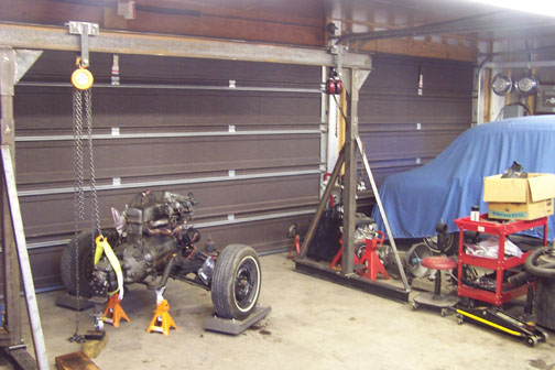
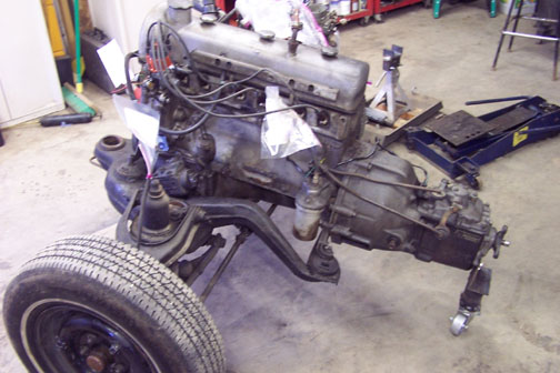
The second photo shows the engine and sub-frame, etc. positioned to start stripping the engine down in preparation for getting it out to the shop. In this photo I’m using the gantry and one of the chain falls as an aid to help support the back of the transmission, so all of the weight isn’t left on the tail wheel. I dithered a bit about whether to send the engine out or not, but there were a couple of considerations that convinced me it makes sense. When I hand-roll an engine I consider to be healthy, I normally hear hissing and gurgling sounds as the engine turns. This one manifests none of that. Further, with the plugs out and thus no compression, it turns really easily – much more so than the freshly rebuilt Triumph engine did when it came back as a long block. So, I think at a minimum I need to have the shop go through this engine in detail and assess what it needs. Are, for example, the big ends of the connecting rods "ovaled" as they were on the Triumph? Are the main and rod bearings good enough to go back in for another 50,000 miles or so? How’s the end play on the crankshaft? Are the rings worn to the point we should replace them, or are the bores ovaled enough that we need to address that? This would be the time, while the engine is out, to be sure, so the journey down the slippery slope continues.

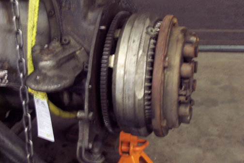
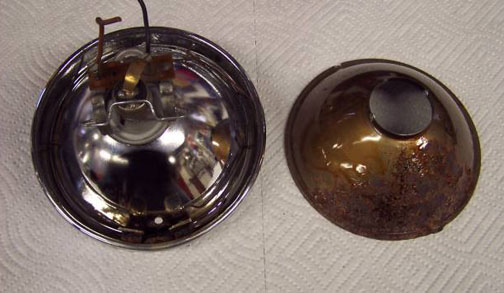
The third photo (apologize for the slight blurriness – didn’t realize it was fuzzy until too late) shows the unique flywheel configuration of a Hydrak car. There’s a lightweight flywheel for the torque converter, then a much heavier plate / flywheel attached to the converter, which in turn hosts the mechanical clutch. I was surprised at how much rust was on the mechanical clutch when I took it apart. I think some of this may have started when the car was stored in a working garage during a Wisconsin winter, and another vehicle was coming and going in that garage in the snow and salt. Looking at the Hydrak bellhousing, it’s well ventilated to ensure the torque converter doesn’t overheat, but that also exposes the workings to humidity much more than a normal, closed bellhousing. I will likely have the clutch disc relined and will also have the pressure plate and cover assembly checked out while I have them on the ground. There was and hopefully still is a good shop in town that can do that work.
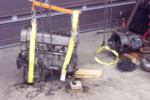
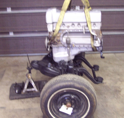
Photo 4 shows the engine clear of the sub-frame and stripped of accessories, etc. and ready to go out to the shop on Monday, which is supposed to be a dry day. The engine needs to ride in the back of a pickup, so weather is a consideration. I’m using nylon lifting slings and my leveling bar to move the engine at this point. I couldn’t find any sling points I was comfortable with for use in lifting, so I opted for some fabric slings so as to not risk marking the engine, oil pan or valve cover. The leveling bar simply lets me keep the engine level, so the fabric slings don’t slip from their intended locations. The center of gravity of the engine as shown is somewhat forward of center, which makes sense considering the weight of the timing chain, sprockets, harmonic balancer, etc.
![]()
Finally, photo 5 shows the now empty sub-frame ready to get cleaned up and painted. There is surprisingly little rust on the sub-frame – none really that I can see. I need to pretty much get the accumulated road grime and grease off, check the engine mounts and get it out of the way until I’m ready for it again. One interesting aspect to all of this was that as I began pulling the transmission, then the mechanical clutch, then the torque converter, etc. off the back of the engine, the center of gravity for the remaining engine and sub-frame was quietly shifting forward – to the point that the sub-frame came really close to simply flipping itself and the engine over frontwards. I needed to stop and get another jack stand under the front to keep it from doing that, and in the end I supported it on two jack stands, one in front and one in back, while I undid the engine mounting bolts and lifted the engine off the sub-frame.
So far, so good. I’m probably not going to like what the engine shop has to say, but we need to do this. I do know, from my father telling me, that the crank has been ground twice and the engine bored once, so if we need to replace components there could be an availability issue for the correct sizes. Yup – there are ways of course to compensate, but never as easily as simply putting in the correct parts if they’re available. Still, as someone remarked, the car deserves it, so we’re off to make it better. I am beginning to think fondly of the day I can actually start hanging things back on the car, as opposed to taking them off.
- Chris
Update / February 29, 2012
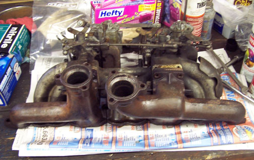
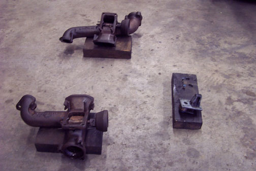
I’m still in the hunt, although we are at the point where the glamour is elsewhere. This is just the grind-it-out part of a restoration that enable glory days ahead — at least that’s the plan. The work recently has been to look at a stuck heat riser valve on the rear exhaust manifold. The first task was to separate the intake and exhaust manifolds. I rebuilt and re-bedded the carburetors not too long before the car was laid up, so elected to leave them in place and break the assembly at the joint between the exhaust and intake manifolds. The first photo is the work of separation in progress.
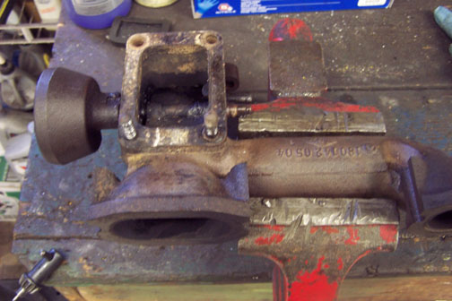
Photo 2 is the rear manifold ensconced in the bench vise. The heat riser valve can be clearly seen inside the chamber that bolts up to the bottom of the intake manifold. Fortunately or unfortunately, this valve is stuck in the closed position. The thermostatic operating springs are both missing, probably rusted off, although it looks as though there should be two – one on each side. My initial thought was to gently remove the asbestos gaskets from the top of the chamber, and soak the manifold in the parts washer until the valve came free or I ran out of patience – whichever came first.
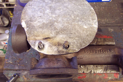
As someone once remarked, it’s always good to have a Plan B. The gaskets seem to be well and truly stuck to the manifold, and it doesn’t help to have the two studs still stuck in the manifold. The third photo is of a heat shield I made out of a scrap piece of galvanized that had been serving as a dust magnet for several years. I heated one of the studs red hot, triple nutted it and it still won’t turn. I also tried heating the manifold, to no avail. Long story short, I’m now soaking the pivot points of the heat riser valve from both sides with penetrating oil to see if that will free it up. I’m pretty sure the asbestos gaskets are difficult to replace, and so I’m reluctant to do anything that might damage them. I can be very patient.
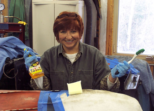
Finally, while I’m entertaining myself fooling around with heat riser valves, my bride Eileen, a.k.a. the "Queen of Clean", has been working in the engine room attacking 54 years worth of road grime, oil weeps and the all important chassis grease that blows up into the engine room after an enthusiastic greasing. Photo 4 shows her standing in the middle of the engine room with the tools of her trade. We both like "Goo Gone" to help cut the grime. I’ve also been working on the sub-frame getting it cleaned up and on the way to getting painted. It looks much better so far – photo to follow when it’s painted and "nice."
Yup – it’s still a journey
Update / May 3, 2012
Apologies for not having written something a little sooner. Spring happened in western New York state, and I took the opportunity to catch up on a little yard work, including cutting up some trees that I dropped into a gulch a few years ago to open up a hedgerow a bit, and taking out a couple of other good size limbs that were a threat to anyone standing under them in any sort of wind. The fresh cut ends represent pieces newly cut to length, most of which will need to be split when they dry out a tich.
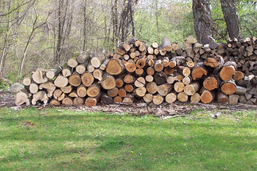
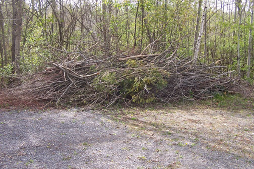
The "chip me" pile of stuff too small to be worth using for firewood grew substantially as a result of this exercise.
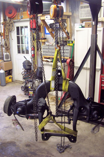
However - the weather turned cold again, and while I did do a couple of things like replace the rear springs and add a front sway bar to the MG Midget, and replace the wiper motor and a worn clutch linkage pin on the Triumph, I've also made some progress on the Mercedes-Benz Ponton sub-frame. The first thing I did was clean and paint the upper side as it sat in the shop. Then, with the upper side at least coated with a rust encapsulator, I hung it from the gantry and turned it over so the underside was facing up. This was done by hoisting the sub-frame vertical, then "dead hanging" it off the gantry so I could "change hooks" to the chain fall on the other side of the gantry, and then using the original chain fall to hoist the bottom up, hold the sub-frame horizontal and gently lower it back down, one end at a time, to the stands again. Nylon sling straps are invaluable for lifting the sub-frame, since they won't scratch the paint or ding the metal. The photo below shows the sub-frame in the air, just prior to dead hanging it and switching hooks.
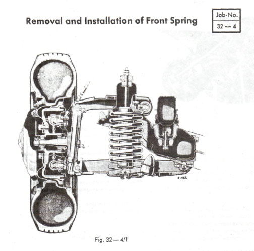
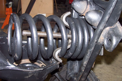
Following the Service Manual (see Job 32-4), I got the shocks out. Of course, one was bad and the other wasn't great, so now I have two new shocks on hand to use when reassembling the sub-frame. Next, I set out to remove one of the front springs to gain access to the inside of the spring tower, which looked pretty rusty. The Service Manual shows a special tool being used that compresses the spring between the upper and lower control arms. The sub-frame is shown in the inverted, or "upside down" position in the next photo. I didn't have the tool, but I did have an axial spring compressor, which goes through the center of the spring (as opposed to the more common "side by side" compressors), and although I could have adapted the axial compressor by extending it with long Grade 8 bolts and a couple of nuts welded together, the hole in the top of the shock tower is only 12 mm, which is less than half an inch - a little narrow for my taste and smaller than the threaded rod of the spring compressor. I didn't feel like trusting the run of the mill threaded rod available from the home stores, so I elected to grab the spring just "below" the spring tower in the sub-frame, and compress it against the lower control arm. That's the top of the spring compressor, with one of the compressor's hooks visible in the spring, in the next photo. I also used a piece of ¼" bar stock to span the hole in the lower control arm where the shock mounts up, since the compressor "almost" fit through the hole in the lower control arm, and I was pretty sure I could get the compressor well and truly stuck in that hole if I didn't make the base of the compressor bigger somehow. The bend in the bar stock attests to the strength in the front springs.
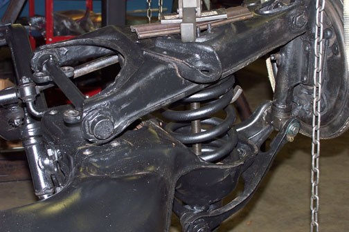
With the spring pressure eliminated to the point that I could get a little independent movement of either the upper or lower control arm, I undid two of the bolts holding the inboard end of the lower arm, per the manual, and inserted my guide rods. These are nothing more than 12 mm rod, threaded on the end to the same thread as the bolts. I took a bolt over to my local fabrication and machine shop so they could match thread and size exactly. With the guide rods in place, I removed the last two bolts holding the lower arm, and then slowly backed off on the spring compressor.
Just like the Service Manual said, the inboard end of the lower control arm rode the guide rods upwards until the spring tension was completely released. At that point I removed the guide rods, swung the inboard end of the lower control arm straight up and sure enough — there was the spring in all its rusty glory.
Note that I'm using one of the chain falls on the gantry and a nylon strap to support the weight of the wheel hub, brake drum, etc. The underside of the sub-frame can best be described as "a mess." There are 50 years of road grime, excess chassis grease and just general dirt caked in all kinds of places. The inside of the spring towers isn't exactly pristine, either. This morning I spent time cleaning up the driver's side of the sub-frame on the bottom side, which is now facing up since I turned it over. It's still resting on roller stands, so I can continue to move it around the shop to get the best light, or to shoot caked gunk towards the door and not the toolboxes when using a wire brush in a die grinder to get the hardest caked masses someplace other than on the sub-frame. I can personally attest to the fact that a wire brush in a die grinder can shoot caked gunk a good 15 feet across the shop. For more liquidity add "Goo Gone."
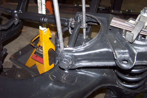
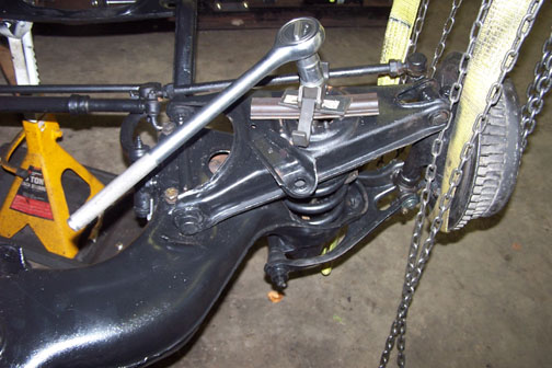
The sub-frame steel continues to look really good. There's a fair amount of surface rust, and some of it has been running under an old undercoat my dad applied years ago. It's not deep, though, and structurally the sub-frame, springs and control arms are very sound. One issue I discovered is movement at the upper control arm outer end, where there shouldn't be any. This is a critical location, since this is the point where the cam bolts are located that adjust the kingpin inclination. This has to be solid, and precise. I took this joint apart, by first removing the clamp that holds the cam bolt in rotational position, then removing the nut from the end of the cam bolt and gently driving the bolt out of the threaded bushing that fits into the kingpin. There is play between the bushing and the cam bolt, so I've ordered an "upper control arm kit - outer", which will provide the cam bolt, the bushing, seals and washers necessary to put this back on spec. I also put a punch mark on the clamp that aligns with where the strike on the cam bolt was when I started disassembly. I won't by any means testify that this will allow me to get the kingpin inclination precisely correct, but it will allow me to get the adjustment "roughly right" enough that I can safely drive the car (some day) to a shop and have a complete front end alignment done. The photo below shows the cam bolt partially inserted in the bushing, which is partially threaded into the kingpin. The clamp, not shown, is nothing more than a bat-wing shaped plate that clamps down on the flange of the cam bolt facing us, and prevents the cam bolt from rotating. The strike on the cam bolt, which is used to re-gain alignment, is shown running from the top of the bolt in the photo into approximately the center. The outer end of the upper control arm, still upside down, is shown at the bottom right of the photo.
I talked with the engine shop last week. They haven't started on the engine yet - their bread and butter is what are termed "race motors" in this part of the world, and spring is a busy season for them. It's just as well, though, since as I get deeper into the sub-frame and suspension I'm effectively pushing out the date when I'll be able to put the engine back in the car, and that's OK. I still think of myself as the steward of the car for the next generation, and that means I need to make it as perfect as I can so the next steward may have less to do. It continues to be a journey. I've got the spring over to a shop in town for bead blasting. Once it's back, and I've installed the new cam bolt and bushing it on the side I'm working on, I'll reassemble that side, including the shock, and do the other side, replacing any obviously worn parts there in the process. Then, hopefully, I can move the sub-frame out of the shop along with the gantry and concentrate on the body. There are, as the saying goes, some things to do there. More as progress happens.
Update / October 15, 2012
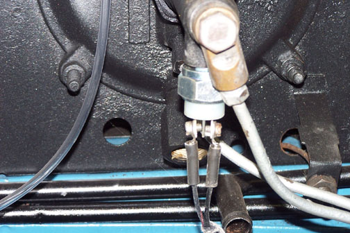
The last time I checked in, I'd found movement in the outer, upper control arm joint where it connects to the kingpin on one side. That resulted in an order to Miller's Mercedes for an "Upper, Outer" joint kit. When I got to installing the kit, I was more than mildly surprised to find that the new threaded sleeve, which should have threaded nicely into the kingpin, went in half way and stopped. Trying to insert the sleeve from the other side produced the same result. With apologies for the blurry photo, here are three sleeves — from left to right the original, the first replacement and an un-forecasted second replacement.
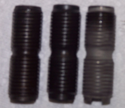
The first replacement sleeve turned out to be "just not right." It's not easy to see, but the thread spacing across the grease groove in the sleeve's center is about ½ pitch off from the other side, when compared to the original and the second replacement. That resulted in the threads not matching up, and thus causing the sleeve to baulk once those threads started into the kingpin. Kudos to Miller's Mercedes though, in that they provided a second joint kit, and free return shipping for the first. The new kit fit perfectly, and with the joint reassembled the unwanted movement that used to be there is gone. An interesting learning from this is that the rotational movement in the joint to adjust for bumps in the road is between the kingpin and the outer side of the sleeve. The groove in the sleeve corresponds to the location of the grease fitting on the kingpin. It's definitely stating the obvious, but I can't emphasize enough the importance of making sure the joints are greased on a regular basis to minimize wear and ensure that a correctly aligned front end, essential for handling, steering effort and reduced tire wear, stays that way. There are 17 grease fittings on the front suspension, including kingpins, steering idler arm on the passenger side and the tie rod ends. I've greased them all.
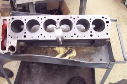
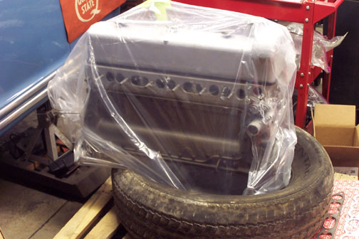
The news from the engine shop was not exactly what I had wanted to hear, but based on how little compression I felt with spark plugs in place, it wasn't really a surprise. We had broken top rings in every cylinder, and some scoring in one or two of the bores. Clearly a mandate to bore the engine, replace the pistons and rings and start over. The good news is that the crankshaft appears to be in fine shape, requiring only polishing and new bearings before getting reinstalled. The engine has been bored once already, to the 85.5 mm size, and we've gone up another half millimeter to 86. In English measurement terms, we're now at .040" over, and we're pretty much at the outer limit now for bore size. The block has been hot tanked and roughed out to the new bore size, as shown below. The funky ring structure in the photo is a lifting sling temporarily installed into a head bolt hole by the engine shop.
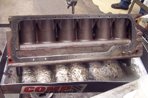
Here's an interesting view of the side of the block. Note the strengthening webs at the tops of the cylinder castings, as well as some cast-in tie bars between cylinders 2 and 3, as well as 4 and 5. The front of the block is on the left in the photo above. The engine shop has ordered new pistons, which are expected in a few weeks. We're going with pistons from Ross Racing, which does a substantial business in custom pistons for many applications. It turned out that going the Ross route saved around $200 per piston when compared to pistons from the Mercedes-Benz Classic Center. The pistons won't be "exactly original," but the engine shop started by locating piston rings of the correct material, diameter and useable thickness, as close to the originals as possible, and then ordered pistons to fit the bores and rings. They'll actually finish-hone the bores to fit the pistons once the pistons arrive.
The sub-frame work is complete. It took some effort to get down to the metal by removing the old grease and dirt, but once there I coated everything with Eastwood's Rust Encapsulator as a primer, and then followed up with Eastwood's Chassis Black. Of particular concern were the spring and shock towers on both sides, but they have consistently been solid under the surface rust. Here's a shot of the sub-frame, bottom side up, with one spring in and ready for the other.
Getting the springs installed is effectively the reverse of removal. There are some touch-up areas that I can see with the flash photograph, which I'll get for sure. I started spring installation by compressing the spring, again using the axial compressor, against the lower control arm. (Remember — the sub-frame is resting bottom side up.)
I had to tap the end of the spring with a rubber hammer to get it into the tower, but once there it wasn't too far out of position, and in a good place to start.
With the spring in the tower, the next step was to get the guide rods installed.
Finally, the control arm can be bolted in place and the spring compressor backed off.
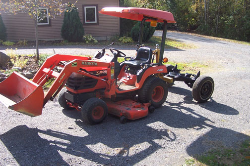
Add shocks, and declare victory. I used the little tractor to drag the sub-frame, now complete and touched up with wheels temporarily reinstalled, over to the barn for the winter, to free up space in the shop.
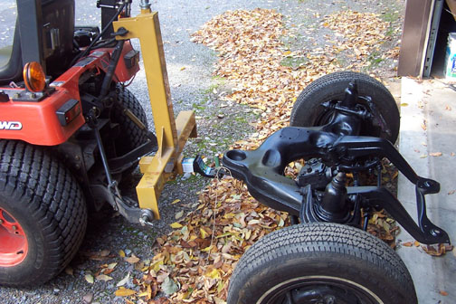
The "drawbar" is nothing more than a trailer ball mount drawbar, but with a bolt in place of a trailer ball, covered in a piece of old garden hose, that the original equipment tow ring slips over. The sub-frame towed nicely for the couple 100 feet or so it needed to travel. Hopefully we're well into putting this all back together in the spring.
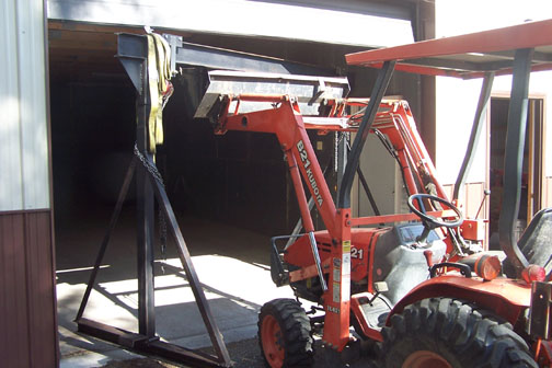
Finally, the need for the gantry, at least for the time being, was no more, so I broke out the big tractor and used it to pick the gantry up and carry it over to the barn as well.
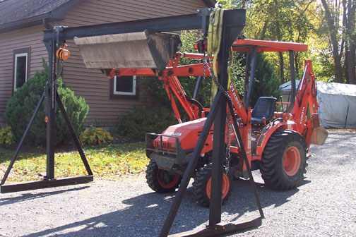
How does an 11 foot wide gantry fit through a 10 foot wide barn door? At an angle, and very carefully….
The radiator, heater cores and clutch are all back from their respective shops. Details on these in the next update. I expect progress to pick up now that winter is approaching, and we're almost done outside for the season.
More to come...
Update / November 19, 2012
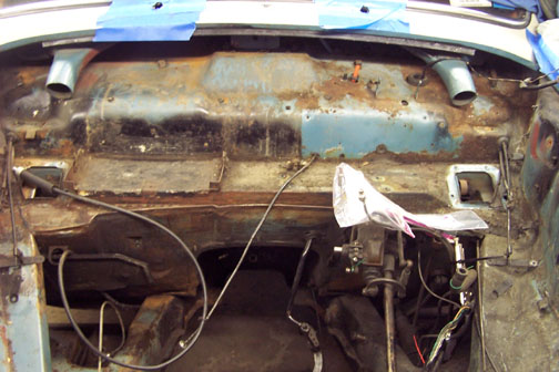
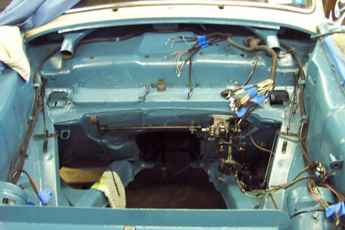
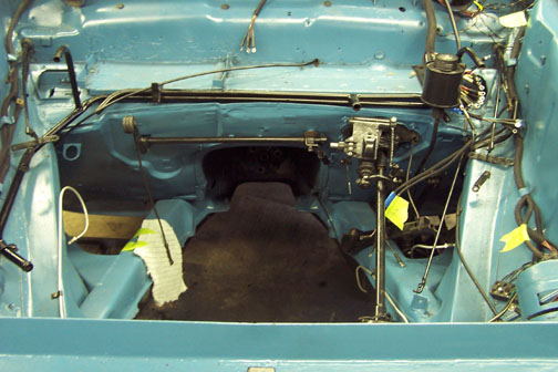
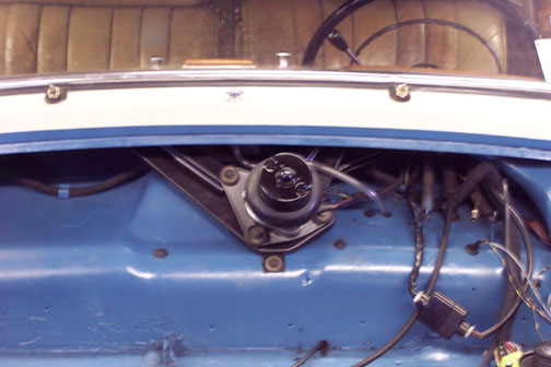
The cooler weather has finally brought most of the yard work to a close for the season, and I'm getting more days in the shop now. I find that I make the most progress if I head out to the shop with a specific goal in mind - get the brake booster off the shelf, for example, or pull the wiper frame. Here's a not great shot of the booster still in the car prior to removal. I took this photo primarily to remind myself, when the time comes, what the connections looked like before I started. There could be some hope of re-attaining the original connections with the help of the photo. The extent of surface rust within the engine room is also readily visible in this shot.
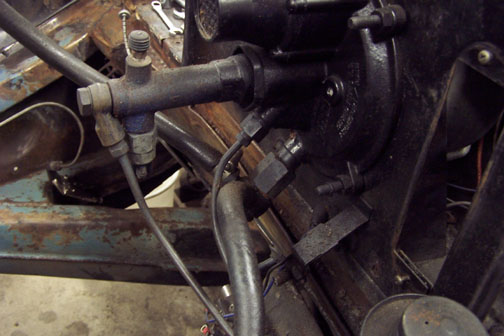
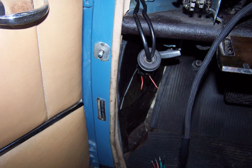
Here's another view of the booster and the steering / shifter column where they come through the firewall. I haven't quite decided if I think it's worth trying to reach the bolts holding the mounting plate in place, or simply mask around all of it. Since contortions are required to get to the bolts, I'm leaning towards the masking approach. This could well change when I start masking. There's also a question whether all of the shift linkage paraphernalia fits through the hole in the firewall without any additional disassembly, but we shall see. I think I could mask and paint around all of this, with a small enough gun, hence the lean towards mask and shoot.
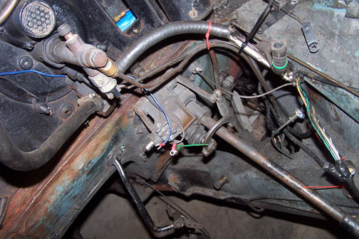
In any event, the brake booster had to come off, and it came pretty easily. My biggest heartburn here was that I've now begun opening up the brake hydraulics, which may lead to some future issues, although everything is reachable with the engine in the car - but with contortions, again. Here's a view of a minor surprise that I found with the booster out. Years back, some mice had built a cozy nest in behind the booster and the dash insulation. Although we thought we'd cleaned out most of it, apparently some things were hiding where we couldn't see or reach them until the booster came out. The shop vacuum came in handy to suck most of this out of the car.
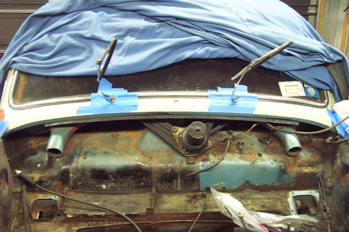
With the booster off, I went after the wiper frame next. Here's a shot with tape on the paintwork to protect it as I got ready to work through the layers of nuts, spacers, rubber fittings, etc.
So as of now the big components, i.e. brake booster and wiper frame, are out of the car, as well as the engine room brake lines, the hood hinges are off and the hood cable has been released from the latch and pulled back a bit. There's a heat shield held by three Phillips head bolts inserted from the inside of the car that of course isn't coming easily, and it needs to in order to free the speedometer cable. With time, patience and a little heat I'm sure it will. I'm getting closer to prep and paint, after which the new harness will start in and we will have, at least with respect to the body, "turned the corner" and started to put the car back together again. I can visualize laying in the new harness when the time comes. Visions are good to have.
There will be some issues with masking the engine room when the time comes - with as many large parts out of the car as I have, and with all of the cables, hoses, etc. ultimately pulled back into the passenger compartment to allow for freedom in swinging the paint gun, I've opened up myriad, it seems, large holes between the engine room and the passenger compartment, which will, if I'm not careful, enable me to apply blue paint in many places where it shouldn't be. I think I'll need to stuff some of the holes, like where the instrument cluster goes as well as the cigar lighter, with paper, then tape over that from the inside, after first lining the edges of the holes, where possible, with tape. There are probably two or so days ahead just masking and checking for leak potentials. Still, I'm pleased with the progress so far and look forward to making more.

In the meantime, the radiator and heater cores have come back from the radiator shop looking much better than when they left, and have been tested to 20 psi.
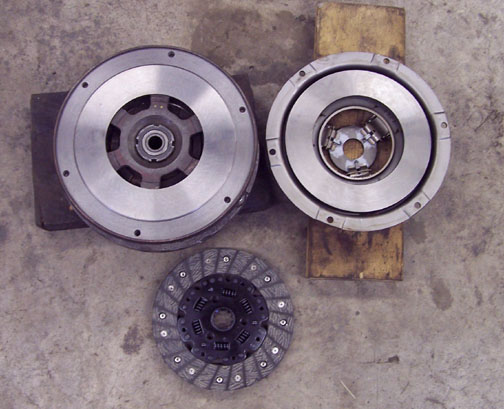
In addition, the clutch has come back. It reappeared with fresh linings on the disc, and nicely refreshed drive surfaces on the pressure plate and "flywheel" (a.k.a. driven surface on the torque converter.)
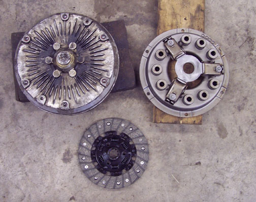
Here's a shot of the same components, "turned over." Again, they all look much better now than when they left the shop here.
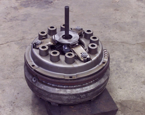
Since it's going to be some time before I'm ready to actually hang the transmission back on the engine with the clutch installed, I put the clutch together using an alignment tool to ensure the disc was centered, and torqued the cover and pressure plate assembly down.
This will help protect the "shiny bits" until they're needed. And yes, I did slip the completed assembly over the input shaft on the transmission and yes, it went on (and came off) easily, so the disc is centered and I'm ready to bolt up the torque converter to the engine flywheel when the time comes. I have a couple of final "notes" to pass on that I've begun to do. Typically, when I need to refer to the shop manual, I make a "shop copy", which, if it gets greasy, stepped on or coffee spilled on it, can be thrown out with a clear conscience.
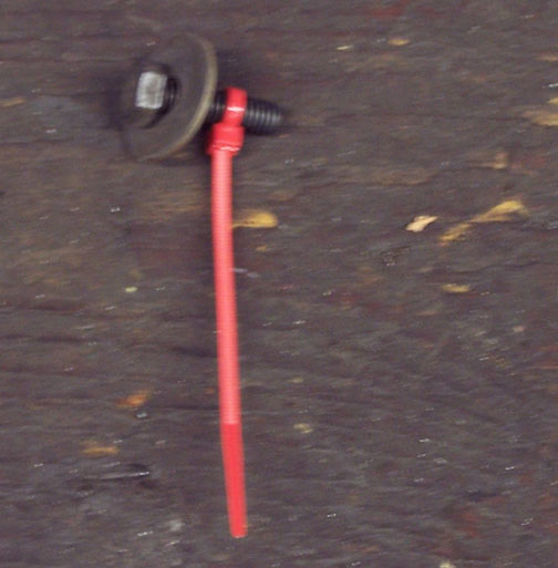
Also, although I "bag and tag" everything, if there's a special pairing of a bolt and a washer but no nut, and the bag is something like "wiper mounting hardware," I'll use a zip tie to hold the washer in place on the bolt so hopefully there's less time ahead figuring out what I can't remember.
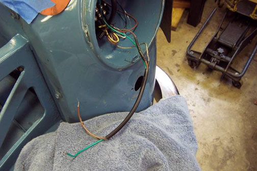
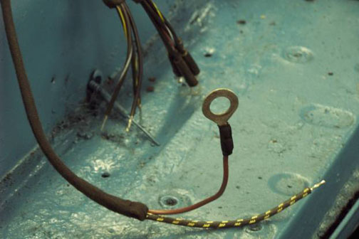
So, there's progress to report and more to make. Somewhere, in the left front fender well, up behind the vacuum reservoir, there's a pair of wires from the engine room that go to what I'm sure is the vacuum solenoid valve that actually operates the Hydrak vacuum servo. The wires are insulated with cloth. The cloth is cracked in places. Inevitably, I'm going to have to either pull the fender (very unwillingly) or pull the vacuum reservoir so I can see if there's a snowball's chance I can replace the wiring without pulling the fender. I've started soaking the appropriate bolts with penetrating oil.
The journey continues…
Update / December 13, 2012
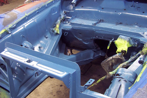
BLUE! Clearly not my spirits, but real paint that matches the car, and for the first time in many a year the engine room is actually all one color. That’s the good news. The news from the underside of the car, though, is maybe not so good.
I’ve done a little scraping on the frame rails, but there’s more to do and paint to come. It sure seems like this is the time to finish this out, particularly where the suspension sub-frame will mate up to the body and hide the surface below essentially forever.
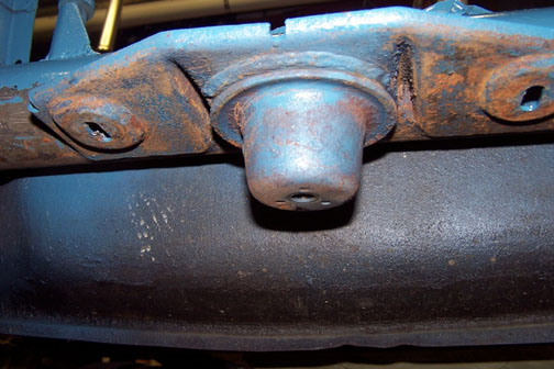
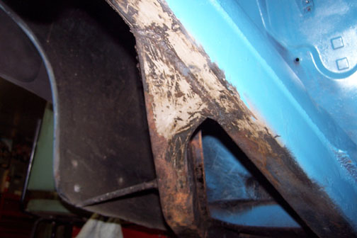
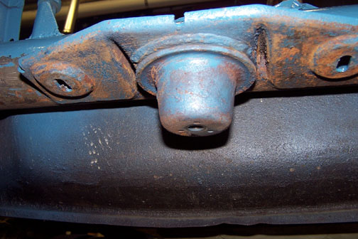
The front "sub-frame mating boss" that drops into the front socket on the suspension sub-frame, as shown below.
There’s a little bit of a quandary in my mind as to what the color on the underside of the frame members should be. From scraps of paint that I’ve found, it seems as though at least the lower half of the major body frame members in the engine room were black. The photos on the Ponton site of cars being lowered into ships’ cargo holds also suggest that the undersides of the cars were black. I’m leaning towards masking off the upper half of the frame members, leaving them blue and doing the lower halves in black. It would be a nice contrast in any event. I’ve found traces of blue on the upper halves, so I think that’s correct, and some blue on the lower halves, but only in the front cross member and sub-frame mounting boss as above, and surprisingly along the lower half of one left frame member but not the right. However, the photo below really "ups the interest factor" for me and possibly explains the anomalous blue on the lower half on the left.
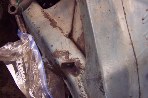
Out of the 50 year old grime, as I cleaned and prepped the engine room, emerged the discovery above. The bracket in the center of the photo holds the fuel tank selector valve (main or reserve.) The bracket used to be closer to the rear of the car, as evidenced by the remnant still on the frame member where it was cut off, and the bracket was clearly moved subsequent to the initial installation. The quality of the weld on the bracket in its current position suggests a "field weld" as opposed to a "shop weld." When I look at my build list, although my German is pretty rusty, it’s not clear that the car was shipped with the Hydrak installed. More likely, the car was shipped with a manual clutch but enabled for Hydrak, and the Hydrak itself was a dealer installation done, in keeping with the family legend, prior to the car being shown at the ’57 auto show in Chicago. I suspect that the bracket was in the way of installing the Hydrak mechanical clutch vacuum operator, and was moved by the dealer personnel when they put the Hydrak in. This would also account for some different paint that was faded differently in the area of the moved bracket, and the paint runs faintly visible in the right of the photo, as well as the blue on the lower half of the frame member in this vicinity. ("Might as well use the can up, Harry.") So, admittedly this is all conjecture at this point, but highly plausible. I’d love to find a way to confirm that the car was actually in the show in its day, but so far all I have is legend, theories and plausible substantiating evidence.
At any rate, I’ve also started cleaning up the transmission.
![]()
I have to admit that I’m impressed with the transmission design. This old toploader is compact, and although there are three shift rods with forks inside, they’re all mounted in the "network" visible on the top of the box. They’re also fully enclosed, and the only vent to the outside is the nicely designed breather visible on the top of the "network" at the left edge of the number plate. A nice contrast to our ’71 Triumph TR-6, which lets the gear lube ooze from the shift rod bushings from time to time. The bellhousing is also interesting in that it’s deeper than normal, to accommodate the Hydrak torque converter as well as the mechanical clutch.
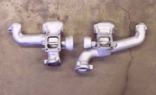
I finally freed up the stuck heat riser valve in the rear exhaust manifold, and both manifolds now have working heat riser valves, although I still need to free up the screws that hold the thermo springs in place – more on this when I can actually show the completed installation. In the meantime, the manifolds are out of the parts washer, and drying prior to painting. I’m toying with powder coating these, in silver to match the stainless exhaust they’ll bolt up to.
That’s the hood latch on the right, which is on its way to being black again.
The engine shop has called, and they have pistons and rings, so I’ve got orders running in North Carolina, California and Germany for bearings, seals, gaskets, etc. We should be starting the engine back together in a couple of weeks, and I hope to be actually starting to put the new wiring harness in place around the first of the year. There’s a soldered "many wire" connector on the harness that needs to be moved from the old harness to the new, and connects the instrument cluster to the harness. That will be a "bench job" and I’ll do it before I start laying the new harness in place.
Nice to be able to report progress – more to come.
Update / February 13, 2013
There is progress to report on multiple fronts — starting with some piston photos.
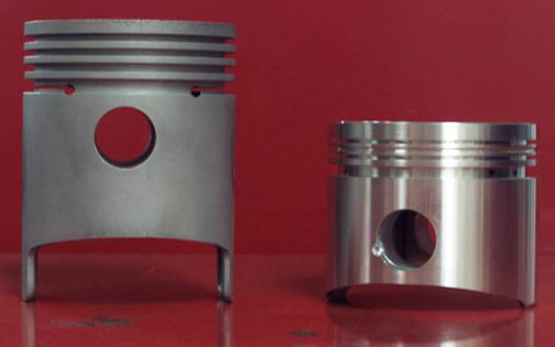
One of the old pistons is on the left, and a new one is on the right. There are some significant differences visible in the photo. The piston on the left uses four piston rings, similar, I’m told, to a mid-30s or 40s Dodge or Chrysler. The piston on the right uses three rings, and additionally has a narrow "entrapment groove" between the top and second ring, which is designed to capture gasses that blow by the top ring and help prevent them from becoming trapped between the top and second rings, pushing the ends out at the gaps.
The other notable difference is the difference in size and thus piston weight. The old pistons weigh in at 466 grams, and the new ones came in at 437. That’s a difference of 29 grams per piston, or a reduction of 174 grams in reciprocating mass that doesn’t need to change direction at up to 9000 times a minute – (I figure 4500 RPM is probably a sensible top useable engine speed once the engine is broken in, and a full revolution is two direction changes – at least in my book.)
The other notable thing about the old pistons is visible in the next photo.
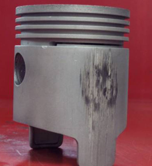
The signs of "piston slap," or scuffing on the side of the piston, is very evident in this photo. We hope, with better rings and shorter skirts, to avoid this in the engine’s next incarnation. The new rings will be moly* as well, so overall, this is an excellent upgrade to modern piston and ring technology that will make the car stronger, last longer, and continue to look original. I couldn’t be happier about this.
*molybdenum – the top and second rings are faced with a moly alloy, which makes them tougher than the iron rings we are all used to. They tend to seat faster and should last longer. An interesting sidelight to this is that the engine shop started with the rings they wanted. They worked with the ring manufacturer to get moly rings in the correct diameter once they knew what the final bore would be. Then, the ring manufacturer knew the folks at Ross pretty well, and had apparently done this a few times before, so they went to Ross and spec’d the pistons to fit the rings and the bores. Ross made the pistons to order. Seems pretty cool to me.
I delivered some manuals and copies of manuals to the engine shop the other day, and they got the head on, the camshaft installed, and the oil pump on along with the strainer.
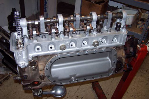
In the photo above, they hadn’t set up the rockers for the last two cylinders yet, but were on their way. The shop also indicated that they had hand cut the gaskets for the side plates. I may need to grease those before I paint the engine, once I get it back, since I think they look nice "showing cork" as they do.
Things on the home front have also progressed.

The photo above shows the completed painting on the frame rails, which are now blue on top, and black on the bottom. The seam where the rail halves were joined together makes a convenient color separator boundary. I’m not sure how original this actually is, but I like the look and at this point that’s good enough. Note that I also have the throttle shaft painted and re-installed, and the shifter, steering column, control cables, etc. are also done. That little piece of towel is there simply to protect the frame rail from the throttle linkage until I’m done on the "shelf" at the top of the firewall, re-installing the wiper linkage, brake booster, etc. I still need to reinstall the brake master cylinder and the "shackle" that connects to the pedal, and yes I intend to paint the inside of the transmission tunnel, but there are some other things I also want to make progress on.
Finally, I screwed up my courage and set to unsoldering the old harness end of the instrument cluster connector.
That’s the connector I’m going to use on the left, plus another salvaged one I’m using to double check the orientation of the connector and wires as they go back together. A little surprise was the discovery of side holes in the sockets where the new harness will get soldered in.
I’d approached this task with much trepidation, but it turns out that a pencil type soldering iron, in fact the one I used to use repairing circuit boards when they were easily repairable, could produce enough heat to liquefy the solder, and then a shot or two of 80 psi air from the blow gun was enough to make the liquid solder go everywhere but in the socket where I didn’t want it. Mission accomplished, and little balls of solder hanging on my work shirt do give it a glittery look. Wait – maybe that wasn’t really the goal. Moving on - the next steps are to get the connector soldered up to the new harness, finish that transmission tunnel, and get the brake master cylinder back in the car along with the front brake lines that I removed to paint. Then, it will be time to lay in the new harness, paint and reinstall the brake booster, go get some new heater boxes, and so on.
Onward!
Update / March 14, 2013
Happy "Pi Day" (Π = 3.14). I seem to be getting some traction at this point. With paint completed, we turned the corner last month and started putting things back together. First came the reinstallation of the brake pedal and master cylinder. The master cylinder sits very low in the car. The open connection on the top of the master cylinder will connect to a brake fluid "make up" line going to the brake fluid reservoir, which is located next to the brake booster. This may be a lot more clear once I start reinstalling the booster and reservoir and can show photos.
That's the end of the steering column on the left, hauled back up out of the way until the engine and sub-frame go back in the car. Next, I hung the harness in the shop to verify the various branches, as well as identify all the branches that had to go through the firewall. I also successfully soldered on the harness end of the instrument cluster connector.
I also suspended the harness, to take the weight off, when soldering the cluster connector onto the new harness. It went pretty well. That's the new connector, installed, housed in the plastic bag to protect it while I turned the harness multiple ways. Not long after this, I laid the harness in the car for the first time.
With not a little exertion, I managed to get the large grommet that surrounds the harness branches that go into the car, in the upper right corner, more or less inserted correctly. A follow-up effort after the grommet sat for a week or two, and after this photo was taken, made it "roughly right enough." I believe it's air tight at this point.
Next, with a lot of exertion and multiple "experiments," I managed to get the first headlight / turn signal / parking light leg pulled into the right front headlight bucket. The terminal strips that should have been in the headlight buckets were long gone - victims, I think, of the shop that repainted the car in the '90's. I think the guys there figured that the terminal strips were pretty corroded at the time, and there were better ways to connect up the wiring than re-use the strips. I wanted to keep the car more original, though, so I adapted my own terminal strips to connect up the headlight wires with the harness wires, but it seemed to work out fine - I was actually able to drill the adapted terminal strip so it fit the original holes. Not exactly correct, but good enough and not visible to the public eyes. I'm OK with this, and my cost for "general purpose" strips as adapted was a lot less than the originals from any source.
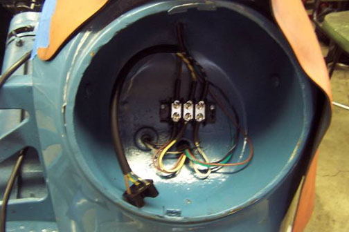
To get an appreciation of what's involved in pulling wire to the headlight buckets, here's a shot of the back side of the passenger side headlight bucket. To get the harness leg to fit through the pipe, the white and yellow headlight wires needed to be folded back alongside the vinyl tube, and pull through as trailing elements. I did use a pull wire that I fed into the pipe first to get the wire into the headlight bucket.
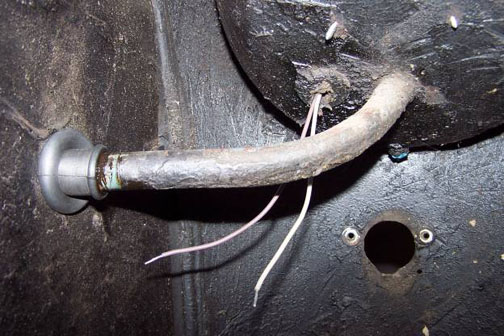
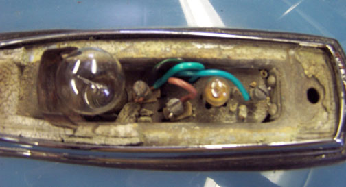
That's effectively a conduit from the inner fender wall to the headlight bucket, sealed by the fancy rubber accordion tipped grommet that fits nicely in the inner fender well as well as over the end of the conduit. This will keep all the wiring dry on its way to the headlight bucket. The two wires hanging down are for the parking light / turn signal on the fender. There were a couple of issues here - one, these wires, no matter what I do with the harness in the headlight bucket, are just too short to reach the socket they need to connect up to. Second, there should be a third wire, since the light fixture contains a two filament bulb with both running light and turn signal filaments. This seems like an issue with the new harness - but no matter. I solved this problem by picking up the turn signal input from the parking light / turn signal fixture on the top of the fender, and running a new green wire down through the headlight bucket and out the bottom grommet on its way to remaining uninstalled fixture.
The green wire "doubled" with the black/yellow wire will carry the turn signal input to the fixture on the front of the fender. I've cleaned up these fixtures and replaced the gaskets since this photo was taken. The fog light reflectors, once I actually took a look, were in pretty bad shape.
These were replaced, and the fog lights wired up and installed. Finally, I extended the wiring for the "bullet lights" on the front of the fenders, using soldered butt splice connectors and heat shrink tubing. Rhode Island Wire provided the connectors and the extension wire, as well as the vinyl tubing I elected to use to protect the wires on their way to the bullet light.
The completed installation for the driver's side looks like this from the inside of the fender well.
That's a little "three bond" gasket maker in gray that I've used to seal the ends of the vinyl tube at each end. After the photo, I did pull the vinyl tube up enough to get the end back into the headlight bucket. Details, details.
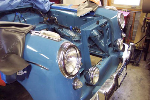
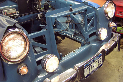
So now all the lights are installed on the front of the car. I'd forgotten how nice it looks with all the lights in place.
The ground wire ring on the new harness was too small to fit over my cigar lighter, so I re-used the old one by unsoldering the ring from the old harness, re-soldering it onto the new harness and completing the job with some heat shrink tubing.
And with that completed, the lighter could be installed. This job seems to require crouching in the engine compartment to even reach the required connections. I'm not sure if my body was ever able to contort enough to have done this from the side and "in the blind" behind the wiper frame, but it sure doesn't contort like that now. This was much more easily done with the wiper frame out and the engine somewhere else, since the lighter is up under the cowl and well behind where the wiper frame will go.
The exhaust manifolds have been bead blasted, the heat riser valve shafts freed up and the riser valve flaps re-welded to the shafts, and painted with a 1600 degree high temperature paint. It may or may not last, but they look nice for now.
I was about to install the wiper switch, with the wiper frame to follow, when I realized that my wiper setup is for a single speed wiper motor and switch, but the new harness will support a two speed wiper and switch. Here's a shot of my wiper motor, which is lacking one more connection that would indicate it's a two speed version (at least per the wiring lists from the harness maker.
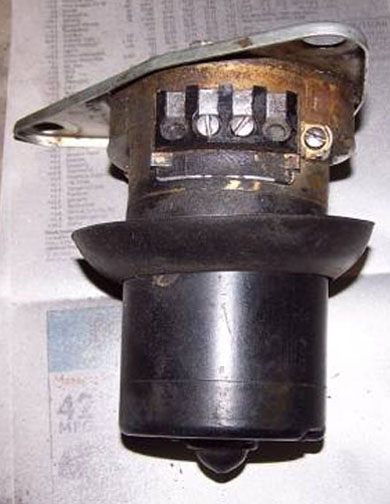
There are locations for terminals, but no terminals. I have feelers out to see if I can (reasonably) get a used two speed wiper motor and switch from a salvage yard. In the meantime the wiper frame needs cleaning and painting, as does the wiper motor, and new heater boxes are in transit. I had intended to get just the shells for the heater boxes and move everything over myself, but when I looked at the amount of time that would take I sent the shells back and ordered new complete units out of Germany. I'm about ready to put those in when they come.
Next on the list is to complete the wiper frame preps, finish the wiper motor and switch wiring, and install those, followed by the wiper frame. Then heater blowers, all the dash switches, flashers, Hydrak relays and wiring, etc. and I should be close to being ready to put the engine back in once it comes home - probably in April or May. I have fond hopes of being able to start shaking the car down in August or September - but we'll see.
Progress is definitely being made - and more to come.
Update / April 17, 2013
It’s been a busy March and April. I found a way to allocate more time to the job, so things are progressing apace now. First off, the coolant pipes that line the edge of the firewall have been sent out, a couple of pin holes fixed and pressure tested. They’re back in the car now, along with the brake fluid reservoir.
It took a little figuring out, and the use of a battery charger to actually energize a couple of wires to "see where they go", but the dome and courtesy light wiring is hooked back up – a little different than when this photo was taken.
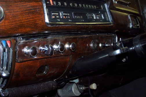
All the dash switches are now hooked up and ready to test.
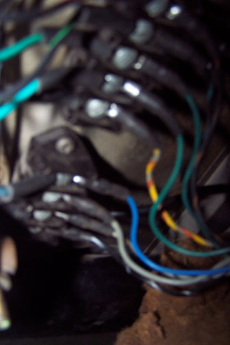
Apologies for the blurry photo (taken lying on my back "real close" to the terminal strip) I’ve done the requisite "dash diving" to complete the connections from the front harness to the rear harness at the junction block under the dash.
So far, so good. I was able to locate a two-speed wiper motor and a two-speed switch. The switch tested fine. The motor ran, but looked tough, so I took it to the automotive electric shop that I use near home and they did their magic on it. The appearance is much improved, and it sports new brushes and a freshly turned commutator. With that back, I installed it on the wiper frame and put the wiper frame back in the car. I should note that in order to actually move the wiper frame in and out of where it needs to go, I actually had to remove the wiper hubs completely from the frame with the frame still in place, and reassembly was the reverse. While the frame was out, I painted it and lubed the gears that turn the hubs. I’ll wait to install the wipers until I can get power to the motor, and ensure that it’s really in the "park" position (nothing like discovering that one’s wipers would really like to clean up the hood to make a good day less good). The new wiper switch, to the right of the ashtray in this photo, is a little larger than the old one, which used to match the cigar lighter on the left. Little sigh, but oh well. I think the two-speed function will be a nice improvement for the car. A fresh run of plastic tubing from the washer pump to the washer nozzles is also visible in this shot.
The instrument cluster is also re-installed, as shown by the connector at the lower right of the above shot. The best news of all, though, is that the engine is back from the engine shop.
It’s been bored, and new pistons and bearings installed. The head was torqued, so it really just needs the auxiliaries installed, like the water pump and manifolds. Thus, no lack of things to do. The plan from here is to mount the brake booster and complete the reinstallation of the brake lines, and then wire up the fuse block and install it. Using a battery charger as a source, I plan to test energize each fuse and the associated circuits, then test lights, switches, etc. and verify we’re good electrically. From there, it’s on to engine work. The radio, a Becker Mexico, is out and on its way to a specialty antique radio shop in the area (Radio Daze). I talked with them and they indicated they were confident they could make it new again. I’ve got a power lead run in to the radio cavity in the dash, which interestingly enough is taken from the hot side of the rotary light switch. Not necessarily how I would have done it, but fair enough – the old one came from there, and so will the new one.
One other decision I’ve made is to abandon (for now) the use of the powered aspect of the radio antenna. My build list for the car indicates that it came with a power antenna. As long as I can remember things about this car, which goes back to 1961, the power antenna has not functioned at all. The wiring for the antenna was pretty tough looking, nothing that I’d like to energize any time soon. For now, I’ve simply cut the wiring off where it passes through the fender wall, and will continue to use the antenna as a manual one, the way we’ve done it since my Dad bought the car in ’61. Perhaps, possibly someday I’ll seek to reinstall a power antenna, but for now that’s much lower in priority than continuing to get the car wired back up and reassembled. Hopefully, wishfully, I might get to the shakedown phase late this Fall. It’s a goal. The journey continues.
Update / November 19, 2013
Summer came, and summer went. Between a wedding for our daughter, a lost month in April for an ill relative and keeping up with the yard work and a few English customer cars here and there, the 220S languished in the shop over the summer. Not that nothing was done, but that I felt there was too little to comment on, at least not worthy of another update. It’s November now, and the grass has (finally) slowed down to the point where I think I might have actually done the last mowing of the year. With the change in seasons, and a refocus of time and effort back to the shop, now’s there’s progress.
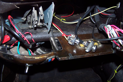
Over the summer, I managed to get the brake booster and fuse block installed. This included connecting the new harness to the fuses, plus adding the brake lines between the booster and the master cylinder. The two flasher units, the largest being for the headlight high beam flasher and the smaller for the turn signals, were also hooked up and installed. Additionally, although not shown, the brake light switch and the backup light switch harness connections were also completed.
I had one problem to solve that I hadn’t anticipated. The new wiring harness came with eyelets for screw connections to the brake light switch. However, the new brake light switch was intended for slip connectors. Electing to see if I could actually drill and tap the new switch and use the old screws, I bought a bunch of taps as the first step, since between my thread gauge and my middle aged eyes I couldn’t tell what the pitch really was. I made a “test plate” using a couple of different thread and pitch combinations, and determined that the actual diameter and pitch for the screws was 4 mm by .75 mm. Drilling out the holes in the new switch a size at a time, and carefully tapping the enlarged holes, let me go back to screw connections, which I like better for wires that hang off the switch as these do. I’m quite happy with this.
The next step was to begin determining how well I’d hooked up the new harness, and how correctly the harness had been built. Turns out the harness is very, very good, but me – maybe not so much. Circuit checkout began at the fuse block, simply powering each fuse supply bus with a battery charger in turn and looking for obvious shorts or bad connections. A short would show up as the ammeter on the charger pinned to the high side, but with the maximum current set at six amps I could save the wiring and the fuses – for the most part. With that step complete, and looking good so far, I then connected the charger to the positive lead in the harness that will some day meet up with the positive battery cable at the starter. Then, I found a few issues to sort out that I had created – two electrical, and one mechanical. The first electrical one had to do with the connections for the clearance lights in the light fixtures themselves.
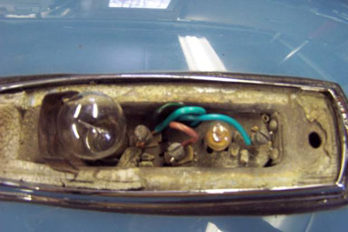
This is an early photo taken before I replaced the
gaskets in the fixtures atop the fenders. If you look closely, that’s the ground wire I hooked up to what should be the hot side of the clearance light, so of
course the hot wire was hooked up to the ground. This cost me a couple of fuses,
but lesson learned – it’s not always physical proximity that identifies the
correct connection. Another tuition payment to the school of life, for sure.
The second electrical issue had to do with the headlight
flasher. It was just on all the time. I think this can be attributed to sloppy
connections on my part up at the flasher switch. A few “flying strays” from the
twisted leads to the switch were probably sharing a connection through the
switch body. Tinning the leads as they should have been, and keeping the ends
short on the off-side of the screw connections cured this one. Finally, the
wiper motor ran a quarter turn, and stopped. I was puzzled. When I pulled the
motor back off the frame, it ran just fine on the bench The answer was a
definite “Duh,” in that between the new motor and old bell crank on the motor
shaft, the bell crank was striking the first actuator rod headed for the wiper
frame, and the issue was mechanical, not electrical. A little bending here and
there, and now the wiper hubs oscillate nicely.
Here’s a victory photo of lights in the car – nice to see those working again.
So, with the battery charger as the power source, I verified all the lights work as intended, the headlight switch and clearance light switches are wired correctly and more importantly – working correctly, and as near as I can tell we’re electrically “done” except for the generator to regulator connection, the coil lead, the horns, the heater fans and the turn signals. All of those are better checked out once the engine is back in the car, which is the next order of business.
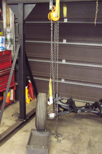
The gantry built to remove the engine and subframe from the car has made a reappearance in the shop, and has been pressed back into service. Step one was to get the engine off the pallet it was sitting on, free up the roller platforms underneath the pallet, which allowed me to move it around as needed, and get the subframe back on roller platforms again.
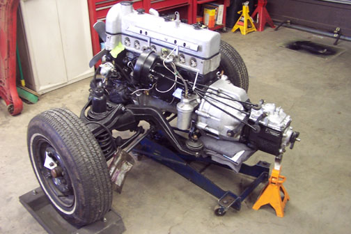
Then, I was able to sling the engine up off the pallet, and move it into place.
So here we are in mid November. The engine is mounted on the subframe, and ready for paint.
The block will be black, the head will be raw aluminum, and the valve cover and pan will be silver. Once the engine is painted, I’ll add manifolds and carbs, clutch and transmission, starter and generator, and we’ll be about ready to put it all back in again. Unfortunately, it turns out that since this is a Hydrak car, I need “green dot” rear engine mounts, which are firmer and necessary to carry the additional weight at the rear of the engine, and what I have now are “red dot.” The red dots are good for the front mounts, and might possibly work at the rear but there’s no way to tell for sure until they actually fail – and I’m not a fan of empirical testing in this case. I have one good source that has the correct mounts in stock, but they’re pricey, and I’m searching for alternate sources. Still, I can begin paint work on the engine with it slung up like this, and simply lift it slightly at the back when the new mounts arrive. In the meantime, inside the car the dash is closed up and all the switches seem to work.
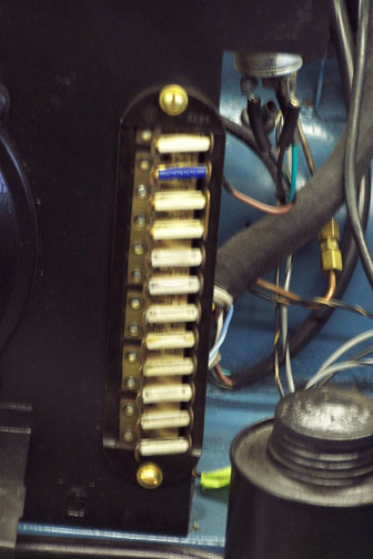
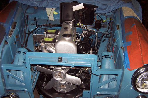
In the engine room, I have correct fuses in every location, and since this photo was taken, I replaced the fuse block cover. I suspect I can have the engine painted by the time the new mounts come, and I also need to assemble the manifolds and get them on the head once the block is painted, along with the generator, starter, et al. There’s still much to do, but on the upside – much of the work from here is “clean” in that the really greasy days are done, and it’s mostly assembly work, which should go fairly easily and quickly. Probably the most time-consuming aspect of what lies ahead is being sure I actually read the manual and put the car back to original condition using original techniques. Two mantras clearly apply – as my father used to say, “if it doesn’t go easily you’re probably not doing it right,” and (even more importantly) “when in doubt, RTFM” or “read the freaking manual.” It’s a plan.
More to come...
Update / January 13, 2014
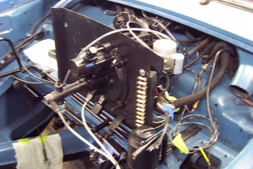
With the engine mounted on the subframe and fresh engine mounts, including the correct “green dot” mounts in the rear, I took time out in December to clean up and paint the various components that hang on the engine and get them reinstalled, including the Hydrak clutch servo. Here’s a shot of the passenger or right hand side of the engine close to installation time. In this shot the front subframe socket, that will host the front mounting boss from the body, is clearly visible at the right end of the subframe, temporarily held by a hose clamp used to keep the subframe securely on the stands as I added engine, fluid coupling, clutch and transmission. The “tail wheel,” which I had used when pulling the engine and subframe out of the car, is also visible to the left. This was a useful technique that I also employed to move the engine and subframe around in the shop as necessary while getting closer to reinstallation. There is yellow masking tape covering the carburetor base plates where the carbs will go. They’re still out for rebuilding, but I expect them back in the next month or so and then can easily be reinstalled with the engine in the car.
This is an older shot of the front body boss, that fits into the front socket on the subframe. Since this photo was taken, the boss has been cleaned and painted and the rubber cushion that fits between the boss and the socket has been installed. The same is true for the two side bosses that fit in the side sockets on the subframe.
Here’s a shot of the engine’s left side. The left side subframe mounting socket is hidden behind the left shock tower. There’s also some masking tape covering the distributor shaft socket, since the distributor will be one of the last things to go in after I use a priming shaft to spin the oil pump with a drill and verify we have oil pressure (and of course check for leaks before starting.) The Hydrak clutch servo stands out in this shot as do the two shift rods to the transmission.
By the time I got this close to re-installation, I realized that my transmission jack would be a good choice for ensuring I had the correct “trim” or front to back height difference when mating the body back to the subframe. I had of course complicated the issue by adding roller platforms under the front wheels without a corresponding addition to the tail wheel, but I felt having the roller platforms would be important and on “Engine In Day” that proved to be true. As a result of my realization, though, I removed the tail wheel and instead employed the tranny jack, with a good sized bath towel dedicated to the shop as a cushion, as seen above. The issue I was trying to mitigate was potential stress and damage to the rubber socket cushion if I landed the body on the front socket first and then forced the front boss and socket to become a rotation point if the trim wasn’t exact. As an added benefit, with the tail wheel removed and the correct bolts back in the transmission tail piece, I drained and refilled the tranny with a largely synthetic ATF, so I don’t expect to need to touch the tranny again until after some shakedown miles (hopefully this summer). The jack stand in the photo was simply “holding its end up” to relieve strain on the tranny jack until the appointed time. Also visible in the photo above is one of the roller platforms I put under the front wheels.
The car was positioned under the gantry and the chain falls hooked up to the lifting or pin blocks about a day ahead of reinstallation. I’d mentioned “engine in day” to several friends and had several offers of help, so I needed to be sure I had everything ready for the scheduled day and time. I meant to take photos of the actual re-installation, but of course got too busy during the process and so the best I can offer is the result. Fundamentally, we lifted the front of the car, pulled out the rolling stands visible in the above photo, rolled the engine and subframe in under the car, and put it all together. Well, it was almost that simple.
Clearances were very tight as we lowered the body back down to the subframe, and the tranny jack proved to be exactly the right tool to get the trim correct. We needed to stop in mid lowering at first when we realized that we didn’t have enough room to clear the Hydrak servo as well as the manifolds at the same time, so we pulled the engine and subframe back out from under the car and removed the servo, re-installing it once we had the subframe mounted back in the car. We executed a reasonable “three point” landing onto the subframe, ran in the three mounting bolts and we were almost done. With all the help available at the time, we elected to also re-connect the steering shaft and pulled the steering wheel wiring harness through the steering box. As a last step, I had the crew help roll the car forward and put the rear jacking sockets alongside the gantry. We then picked up the rear of the car by the rear jack sockets and set the rear axle on roller stands, although we left the chain falls hooked up for redundant safety concerns.

“Engine In Day” was a Saturday, but with the back end of the car elevated, and a very warm day for our part of the world on Monday, I opened all the doors to the shop for ventilation, slid under the car and managed to get gas the tank drained and out of the car.
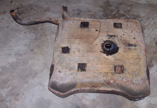
It’s not pretty, but it’s fairly solid overall, and I think a good lining job and some fresh paint will fix what ails it. I’ve left a message with my radiator shop, which also lines tanks, asking when I can drop the tank off to get lined. However, with the tank out, the view under the car where the tank had been was also not so pretty.
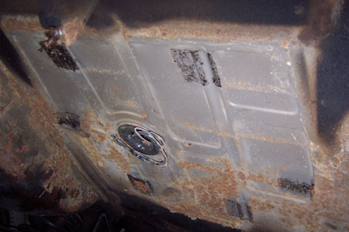
Those plans I had for staying relatively clean from back then? Well, maybe not quite yet. This will need cleaning up and painting before the tank goes back in. I probably will also when done – at least cleaned up, but I’ll probably already be painted.
So - that’s where we sit for now. While the tank is at the shop getting cleaned and lined, I can connect up the drive shaft and brake lines, get the horns and radiator in, re-install the heater boxes and hoses and whatever else I’ve forgotten to list. There’s still work to do, but we’re getting closer.
One other item worthy of note – ever since I’ve had the stewardship for the car, it’s been missing two cover plates on the bell housing – one at the lower left side, and one underneath in front of the flywheel. The one underneath was simply a screen, and the one on the lower left side was supposed to be a “thermally controlled ventilation door.” Only thing is, I don’t ever remember seeing that door on the car. Furthermore, I’m guessing that was a failure point many moons ago, and was removed for cause when it failed. Given that this will at best be a three season car, and that ventilation is important to keep the fluid coupling cool, I wanted to ensure these cooling ports were open all the time. I don’t foresee the need to close one in cold weather, because I don’t expect to have the car out when it’s really cold, but at the same time I also want to keep stones, sticks and other unfriendly things out of the bell housing. It seemed at a minimum I should at least put some “stone strainers” over both openings. Lacking parts and a better idea, I made and took some patterns to my local fabrication and welding shop and the photo below is the result.
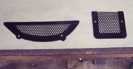
Problem solved for now. These were installed the day before we put the engine and subframe back in the car, so I think this can be crossed off the list. There is still more to come and more work to do, but getting to shakedown mode this summer is starting to look like a realistic goal.
The journey continues. Updates as there are things worth sharing.
Update / February 10, 2014
There are a couple of insights worth passing along at this point. I have to confess that I’ve been in a state of denial about the rear wheel camber of the car since I’ve had it. Unloaded, the car had negative camber, i.e. the rear wheels tilted in at the top. Loaded, with passengers in the rear seat, it really had negative camber. I had the rear springs replaced back in ’93 or so, thinking that possibly the original springs were just tired, but that didn’t seem to make a difference. Lo and behold, though, in the manual there’s a description of an adjustment that can be made to “tune” the camber. The camber issue was brought back into focus by a pointed comment from one of the engine installation crew who noted uneven tire wear (side to side) on both rear tires. Fair enough – with the tank out and the back end of the car in the air, now seemed like a good time to address the problem.
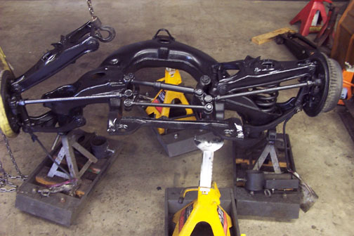
A little explanation might be in order. The “swing axle” rear suspension consists of two floating axle ends, supported by coil springs and a shock absorber at the outboard ends, and fixed in the fore and aft dimension by a “torque arm” at each end. I think the torque arm also prevents the axle from rotating under heavy acceleration or braking. Here’s a view of the left rear side, with the rear of the car still elevated from the tank removal and a chain fall connection off the gantry just to make sure the car doesn’t quietly slide off the jack stand when I’m under it and not particularly looking.
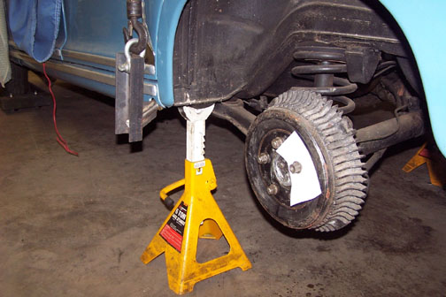
That’s the torque arm connecting up to the bottom of the unibody in the photo. The note card is a shop practice I’ve initiated to remind me that the lug nuts aren’t tight – It goes on when I first pull a wheel off, and stays around until I complete hand tightening. I’d rather over achieve in this area than under. I’ve found that it’s too easy to forget to tighten up the nuts after a long layup and bad things could happen right after that.
Here’s a page from the manual that shows the spring, torque arm and lower spring plate setup, and includes a discussion on recommended notch positions for the lower spring plate.
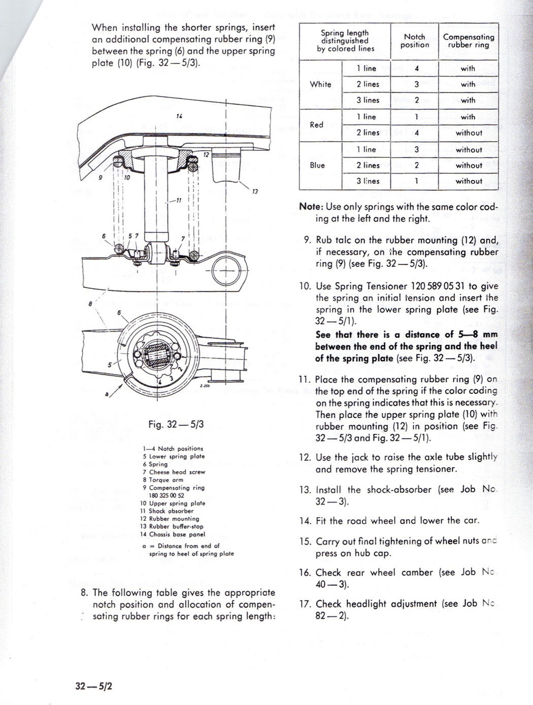
I wasn’t able to find any color codes on the replacement springs I had, but given that the lower spring plates were in the number 3 notch and I had negative camber, it sure seemed like I should try the number 4 notch. I also decided this would be a good time to pull and paint the rear springs. The shocks have to come out first – more on that later. I pulled the springs, one side at a time, using the axial spring compressor again going right up through the torque arm and the center of the spring from the inside. Here’s a shot of the left lower spring plate as it looked when it came out - pretty rusty and not in the best of shape, with barely legible notch numbers. I elected to replace both lower spring plates on general principle.
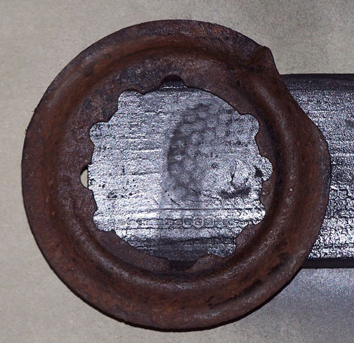
Back to the subject of shocks again. Once I got the old ones out, it was easy to decide to replace them – they were pretty rusty on the outside, and they had little resistance left. In removing the old shocks, though, there was another nasty surprise. The shocks are held in place by locking nuts to the top of the shock piston rod at the top, and the shock body at the bottom. Under that bottom locking nut, though, there is a four hole plate that bolts up to the underside of the torque arm. To my dismay, I found at least one broken bolt of the four on each side of the car, and I successfully broke another on the passenger side during removal. Fortunately, new bolts are available, and I was able to get eight of them just in case. Here’s a shot of the broken ones, next to a new one of each type. I also used new nuts and lock washers when reassembling.
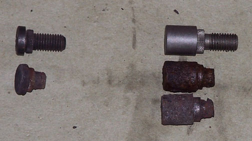
The bolts seem to be a press fit into the torque arm, with a serrated ring to hold them firmly in place. After removing the spring, I was able to get a good look at all four bolts in the torque arm, including the broken ones. At first, I thought I might be able to just whack the broken bolts out from below with a hammer and a center punch. Good idea, but not so easy to do. My next thought was to simply remove each torque arm, take it to the shop press and press the broken bolts out. After I reviewed the procedure to remove the torque arm, rationality suggested a Plan C. I settled on a gear puller, used from below, to hang on the torque arm and simulate a press.
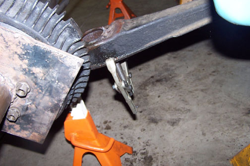
I did need to use the center punch to get an indentation that the point on the gear puller’s shaft could use to hang on to, but the process worked well enough that I managed to get the broken ones out and new ones inserted. The reason for the difference in bolts is that two of them are used to locate the rotational position or notch number for the lower spring plate, and two are there simply to hold the lower end of the shock in place. Here’s a shot of one of the old shocks, hanging from the shop stool, showing the four bolt holes used to hold it at the underside of the torque arm. In the photo, you can see that three of the bolts and their lock washers were just recently removed, and the fourth one has been gone for quite some time. The shocks I took out were replacements for the originals, and I’m guessing that whoever put those shocks in had a tough time getting the originals out, and decided that three bolts on each side would be “good enough.” That’s now no longer the case as I have four good ones holding nicely at each side.
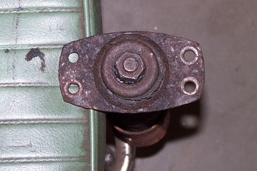
With new shocks and spring plates installed and the camber now correct, it’s another milestone. In the meantime, there are some other things that need attention. I checked out the turn signal circuits, which were pretty pitiful when hooked up to the turn signal flasher, and concluded that I have a bad flasher with symptoms of a loud buzzing sound from the flasher unit itself and pretty random and very rapid flashes when attempting to signal to one side or the other. The symptom was identical on both sides. A replacement flasher is on the way.
I also (finally) sorted out the horn circuit. This car has the optional three tone horn option, a factory add-on described by the shop manual. However, there was also a “contactor” associated with the three horn circuit, along with a push-pull switch under the dash. Based on what I’d been told years ago, I had assumed that the push-pull switch, which selected a relatively mild tone or a really loud tone, was in fact a changeover switch that selected one horn or the other set of two. In fact, as I drew pictures of wiring based on shop manual descriptions, and as I finally opened up the contactor, which appears to be really, really dead, I concluded that the contactor is nothing more than a horn relay for the third horn. The changeover switch puts that horn in the circuit or not, and the relay actually activates the horn if it’s in the circuit. The horn switch will pull in the relay if the push pull switch has the relay connected, and the third horn stays off if the push pull switch disconnects the relay. Eminently simple – once I understood it. Here’s a shot of the relay disassembled on the bench. I couldn’t get it to do anything, so I carefully pulled it apart to see what was actually inside.
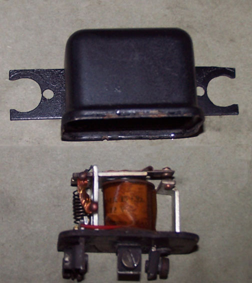
I couldn’t measure any conductivity through the coil, so I took it to my automotive electric shop that I use from time to time and asked them to look at three possibilities – price out a replacement if they can get one, price out a replacement coil if they can get one, or take one of their small, off the shelf relays that they stock, fit it to the same connections on the baseplate and put the can back over the baseplate. They said they’d let me know. I think I can wire this up now, though, and test it by jumping around where the relay should go, so I’m close to crossing this one off the list. Hopefully by the end of this week.
Finally, I got frustrated that I still haven’t gotten to hook up the driveshaft to the transmission, hook up the speedometer cable, close up some cover plates on the underside of the car, and so on. With the help of a house guest pressed into service, we put the rear brake drums on the flange plates and pipe extensions I’d used earlier, put the pipes into rings on roller stands, and shifted the car back in the shop until we could connect the chain falls off the gantry to the front jacking sockets. They we lifted the front of the car to horizontal, put some additional stands and wheel ramps under it, and called it a day.
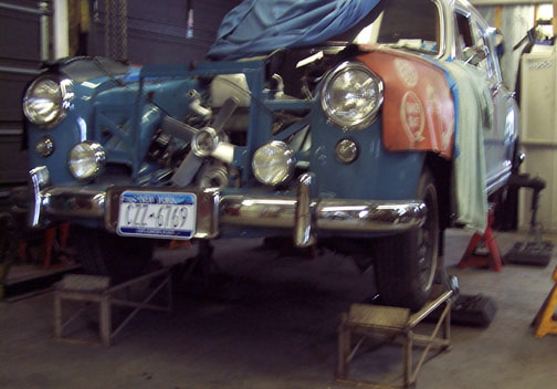
From here, I can do the remainder of the underside work and even get the radiator back in. As always, there are still more things to do, but there is progress and the list continues to grow shorter. It continues to be a journey.
Update / March 14, 2014
This has been a pretty good month for progress, and as this phase comes to a close there are things that are gratifyingly done, some that are “sorta done”, and of course still a few things not even started.
Some of the open items from last month have come to closure. My electric shop informed me that a relay requires a battery to operate it, and a battery charger won’t cut it. I believe I’ve actually tested that now, and I can confirm that the principle is true. My guy at the electric shop said it has something to do with the capacitance of the battery. I suspect what he means is that a battery can support the inrush current that the coil needs to actually pull in the relay, whereas my charger (even at the 6 amp setting) is not set up to do so, and the coil won’t generate enough force to pull the contacts when using the charger. As the saying goes, “learn something new pretty near every day.” With that established, I wired up the circuit as I’d drawn it and yup I had either two or three horns working. But then, going through the parts car to see what was left, an exercise more to see what things should go into the parts washer and come out to get painted – something of a “where the heck is the critical path” exercise – I found another, electrically identical relay. I remember this one hanging on the inboard side of the driver’s heater box years ago, and had originally thought this was part of the Hydrak system. Uh, not exactly, since there’s no relay shown in the Hydrak drawings. Nope, this was a second horn relay. Then the bulb went on in my head. With a second horn relay, and another hour or two of head scratching followed by pen scratching on paper, I figured out a circuit that would make my horn changeover switch truly be an “either – or” switch as I remembered it. It just needed two horn relays.
So now, with that circuit implemented and tested, the horns work as I remember. To pull this off, however, I needed to break out the wire that goes from the negative side of the horns up to the horn switch on the steering column. My recollection is that this was spliced on the fly, or at least I remember some “un- Mercedes-like” wiring when we started stripping the old harness out. I elected to obtain a second terminal block for the steering tube connection, and mount it in close proximity to the first, under the driver’s side heater box – or at least where the box would go if it were installed.
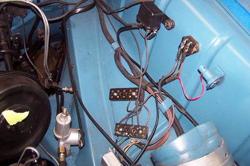
That’s the horn relay for the third horn hanging on the inside of the fender wall, with the negative side horn wire made up to the new terminal block as well as an additional ground connection that seemed like a good idea while I was there. The oddly placed wire with the red tie wrap on it is actually coming from the horn changeover switch, and will be used as the ground connection for the coil of the second horn relay since the changeover switch selectively completes or breaks the coil ground connection for each horn relay.
My guess is that someone in the car’s past probably installed the circuit as the manual describes, “two some or three some,” and was then subsequently asked to make it “either – or” That would explain why the second horn relay was hung on the accessible side of the driver’s heater box, which is where I put mine. There’ll be a photo later in this update.
With that lead-in, though, let’s talk about heater boxes. Mine were in pretty bad shape. A mouse had set up residence in the car many years ago while it was “stored, pending restoration” and before I had it in my possession. I decided that the best alternative was to order two new ones, complete with dampers.
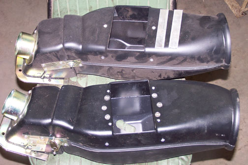
The boxes got a little dusty sitting around in the shop for a while, and the flash mechanism on the camera highlighted the dust. The first thing I noticed about the new boxes, when I got them back up on the bench, was that there wasn’t much metal to tap threads into in order to tie down the heater cores. I elected to put aluminum bar stock into the boxes to reinforce the thin metal strap that the box comes with. I used metric flat head socket head bolts, drilled and tapped the aluminum bar stock, and bolted the new bars in place. Then I drilled and tapped the holes for the heater core mounting bolts. In the photo above, the upper heater box has the bar stock cut to length resting on top of the box, and the bottom box shows the result with bar stock installed and holes drilled and tapped for the mounting bolts. The heater cores will cover all but about a third of the center bolts when installed, and I can live with that for the additional strength and security this provides. Heck, I might even paint them black.
Here’s a look into one of the boxes showing how I put nyloc nuts under the bolts so they should (presumably) never loosen.
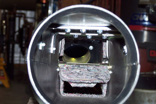
With that work complete, I added another aluminum bar on the exterior inboard side of the driver’s side heater box, also tapping into the existing strip that came with the box, and used that to mount the second horn relay. Here’s a shot of both heater boxes in the car, and the second horn relay mounted almost opposite the first.
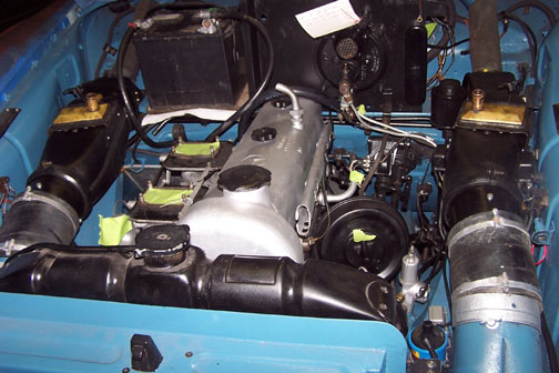
To be completely honest and open, a couple of things in the above photo are misleading, so let me clear that up. The heater cores have been stripped to reveal that they have brass tops. I love it. However, they’re just set in place to keep them safe for now. After a three week sojourn to warmer weather and anticipated good times with old friends as well as Eileen’s brother, a very cool guy in his own right, I intend to apply brasso as required and clear coat afterwards to ensure those brass tops are even nicer looking and will most likely stay there. There’s also one more bolt I need to install on the driver’s side heater box. It’s the long one that comes up from inside the car into a receiver socket on the side of the box. The hole didn’t quite seem to line up, but it did on the passenger’s side. I’ll need to address that as well when we get back, around April 1 or so. However, as one can see from the above photo, the radiator is in, and I’ve gone to using a temporary battery, one that’s not correct for the car but puts out 12 volts when I need it, so I can test relays and such. There is also, but difficult to see in the photo, a battery ground disconnect switch at the top of the negative terminal, so I can put power on the car if and only if I think it’s a good idea at the time.
Once the heater boxes are fully tied down and the cores bolted in, I can start to “hose up.” This feels like it’s getting closer. The carburetors, I’m told, are done and should arrive while we’re gone. The gas tank is still out for repair but that shop moves to its own time, and far be it from me to interfere at this point. I’ve pulled the front seats and rear bench out of the car and taken them to the upholsterer’s. We’re going to re-cover the front seats since they were about done. Stitching was starting to tear, and the leather panels showed signs of extensive use. I also asked the upholsterer to re-do as much of the stitching on the rear bench as he could comfortably do.
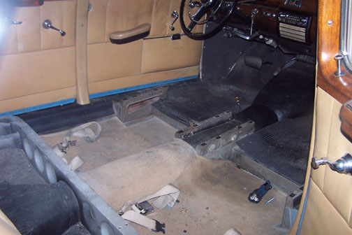
I found some corrosion that needs treating in insides of the rocker panels, now exposed with the seats out, and on the seat mounts themselves, that I’ll also need to address when we return. Might as well hit everything we know about before we put this car back together and back on the road.
Under the car, I did hook up the driveshaft to the transmission as well as the lower end of the speedometer cable, and clean and paint the area above the gas tank. When the tank comes back I’m ready for it. I’ve also hooked the front brake hoses back up, put brake fluid in the system, and bled the brakes. So far, it’s holding fluid, i.e. no purple puddles under the car. I’ll test braking effect at each wheel before I put the car back on the ground and fix anything I find there. For brake fluid, I’m using Silicone DOT 5, on the grounds that this is a car that will spend more time sitting than running, especially in the winter months, and moisture in the brake cylinders will not do me any favors. For all of the issues that come up with DOT 5 when discussions start, I’m of the opinion this remains a good choice for a car that’s not expected to be driven hard and will rest more than run, as near as I can predict. I’ve run DOT 5 for years in other older cars and can say with certainty that I’ve had significantly fewer brake and clutch hydraulic issues since going to Silicone. It’s hydrophobic, or water repellant properties, help minimize rust damage in the cylinders, and that fits my design point.
There’s one additional issue that just came up in conjunction with the front seats. From the time we’ve had the car, it’s had large, factory option headrests.
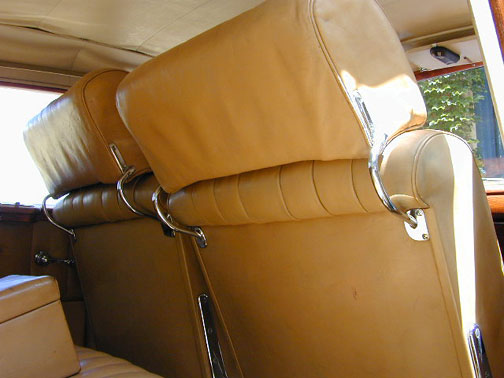
As can be seen, they’re held in place by nicely curved bright steel arms that insert into sockets in the seat backs. The upholsterer called me to say that one of the socket base plates was broken. Come to find out, not only was it broken, but...
a) It didn’t match the other three in the car
b) These things are scarcer than hens’ teeth, so...
c) Big *sigh*
All may not be lost, however. Here’s a photo of the offending socket next to a correct one.
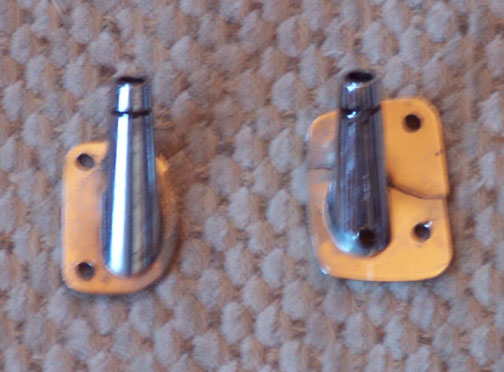
Sorry the photo’s a little blurry, but it’s apparent that the one on the right, with the broken base plate, doesn’t match the one on the left. I dropped by my local fab-weld shop today, a place that I think given sufficient time, can make anything, to discuss the problem. They think these things are aluminum, and if so they can be welded. What they propose to do is try and weld on the broken one and see if the weld is strong. If so, and a big IF that is, they’ll then cut the tube off the broken one, make a new base plate to match and reverse the one on the left, and weld the old tube onto the new base plate. Then they’ll send it out to get plated. It’s a plan, anyway. More to follow on this as it evolves, to be sure.
So, the beat goes on. As always, there is still much to be done. I’m having nightmares that where I located the second horn relay is where the Hydrak control valve needs to go. I may need to invade that heater box and install a third piece of overhead bar stock to provide holes for a new location, or build an “extender bar” that looks original and isn’t but moves the Hydrak valve inboard enough to clear the horn relay, or something else that I haven’t thought of. I suppose I could relocate the horn relay, but I’ve already put holes in the heater box to hold the relay, and I’m not anxious (yet) to try and fix that if I don’t have to. It remains an option, but for now less attractive until I actually clean up the control valve and get ready to install it.
Anyhow, more to come, but not for a while. Herself and I are out of here for the south. Winter storm Vulcan passed through on Wednesday, and even I, the inveterate lover of all things northeast, might actually be ready for some warmer weather. It’s a thought. In the meantime, the journey will continue, right after a little intermission.
Update / August 14, 2014
Once again, spring and summer happened in western New York, and with them came yard work, some customer cars, some recreational driving, and of course the odd thing or two on the house, or the machinery, or another member of the vehicle fleet that "really needs doing right now." The 220S restoration project languished a bit, but didn't stop, and at this point we're "almost there."
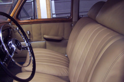
Just before we left on vacation, my fab-weld shop determined that the headrest mount with the broken base plate couldn't be welded. As a result, the consensus was that we would have to have them actually make one from scratch and send it out for plating, so they did. In the same general time frame, the upholsterer finished installing the new skins on the front seats, which are now back in the car with the headrests in place and all headrest mounts matching. The front seats look great at this point, and I suspect we'll get the back seat done next year.
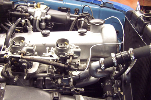
The carburetors came back from their rebuild and have been installed. I've ordered a new fuel line to go from the pump to the carbs, but it's back ordered. Until it comes, I'm using the old one, which looks nasty but is fully functional, and I've left the vacuum line to the distributor "flying" until I can strap it to the new fuel line once installed.
The gas tank came back patched and lined, and with a freshly painted filler neck went back in the car. Something that hadn't been on the list to do to this car when I started this project was the addition of an electric fuel pump. It made sense, though, since from the time the car has been in the family, and in particular since it was painted and the chrome re-done back in the '90s, it has been very hard to start after sitting for a while. Seems like the gas evaporates from the float bowls in the carburetors, and the mechanical pump, which is still in place, needs quite a bit of cranking time to get the float bowls refilled. I do quite of bit of work on the smaller English sports cars – e.g., MG and Triumph, and with their electric fuel pumps we've never experienced a similar problem. The "start" process for my '72 MG Midget is to turn on the ignition and listen for the fuel pump to start clicking. Then wait for the sound change that indicates the carb float bowls are full, and hit the starter. The more I thought about it, the more I liked the idea of a similar process for this car. However, I wanted to accomplish that without altering the car's look of originality.
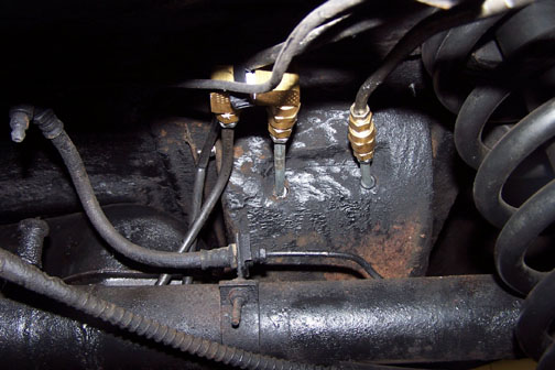
The discovery of a second, unused spare tire well on the driver's side of the car made the installation relatively simple. The first thing I did was "invade" the main or high suction line after it left the tank, and with some brass fittings turned it so it went through some new holes and grommets into the previously un-used spare tire well.
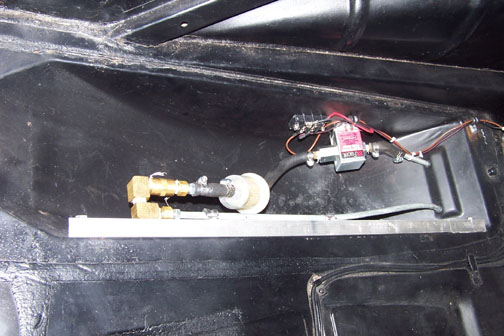
Then, in that well, I installed a "Facet" electric fuel pump purchased from Moss Motors, a large supplier of English car parts, an additional fuel filter and a terminal strip. I chose the terminal strip as the means to connect the pump electrically so as to stay consistent with the other electrical connections in the car. I put my own eyelets on the end of the wires, soldering them first and then sealing them with heat shrink tubing. The electric pump actually pumps through the mechanical pump, which once the car is running can also pull through the electric pump. I also like the redundancy this provides, since we may well do some touring in this car.
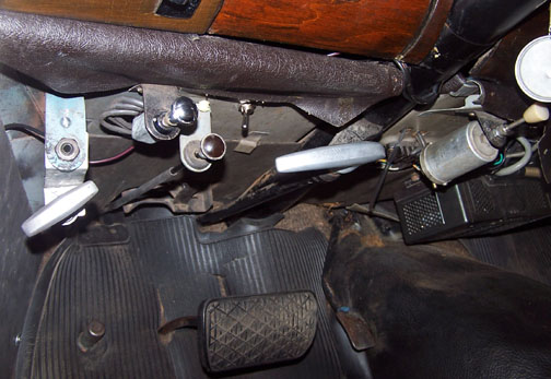
Under the dash, where it's difficult to see, I located a switch for the pump and wired it to fuse 2, the largest capacity one.
Then I ran a long wire down the side of the cabin, under the carpeting and under the rear seat and into the trunk and then to the terminal strip in the spare tire well. Normally, I like to switch the ground side of electrical circuits, but in this case the wire run was long enough that I felt better having a positive current shut off should something go amiss, rather than relying on a ground side switch which, in the event of a short somewhere down the line, might cause the pump to run when I didn't want it to.
The output side of the pump is then connected to the remaining part of the line going forward to the fuel selector valve and in the engine room the modification is undetectable from a casual observation. And, by the way, it works great.
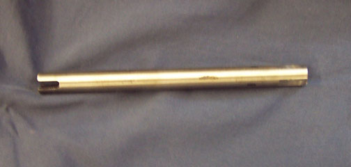
With the radiator full and oil in the sump, and no apparent leaks, I turned to getting the distributor back in the car. The first thing I did was get out the priming shaft for the oil pump that my engine shop had made for me and spun the oil pump to confirm that I could generate oil pressure and not encounter any significant leaks. One end goes in the drill chuck, and the other fits over the top of the oil pump drive.
To complete the next step, which was to drop in the distributor / oil pump drive shaft, I needed to roll the engine over by hand so the helical gears would engage and the slot in the drive shaft would find and engage the top of the oil pump shaft. Turned out the engine was so stiff, due to new rings, pistons and bearings, I had to actually put a socket on the crankshaft pulley nut in order to turn the engine. And, of course, to do that the radiator had to come back out. Of course. I suppose it will ever be thus.
With the distributor installed, I verified the engine would make oil pressure on the starter, to ensure that the distributor / oil pump drive shaft really was engaged in the oil pump shaft. So far, so good.
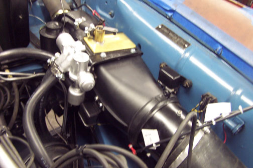
Finally, I turned my attention to the Hydrak. Now, of course, in looking at the wire and terminal list, there really is a relay involved in the Hydrak system, and I'd already thoughtfully turned mine into a horn relay. Not only that, but yes I had mounted the second horn relay right where the Hydrak control valve should go. Well, I like the horn circuits as they are, so I found another relay. I concluded that the lesser of all evils was to relocate the second horn relay to a little bit farther forward on the heater box. I elected to leave the screws formerly holding the second relay in place. Fortunately, they're covered for the most part by the Hydrak control valve. Of course, to get back into the heater box the heater core on the driver's side had to come out and of course I needed to drain the cooling system again.
I was fortunate to be able to locate a reprint of the Hydrak shop manual, which included useful information such as wire and terminal connections along with trouble shooting guides. With the components finally in place, I ran air brake hose for vacuum lines (stiffer walls for a vacuum application without collapsing) and wired up the components to the new Hydrak harness I had made. A cursory test at least produced sounds that seemed roughly right, so it was on to see if I could actually start the engine.
It wouldn't catch. I had fuel pressure, and it cranked on the starter, but although I would get some minor "skittering" it just wouldn't come up and run. As a simplification step, I hadn't bothered to check the ignition timing, since I'd done nothing to the distributor other than paint it before reinstalling it. Uh, dumb idea. When I actually checked the static timing, it was way off and late - possibly contributing to the hard starting noted earlier. In any event, with the engine now timed to 8 degrees of static advance, the engine came to life for the first time on July 31.
I managed to get about 15 minutes of run time in on the new engine before I noticed an oil leak at the front of the engine which was bad enough that I had to shut it down. On closer examination, I determined that the leak was coming from the area of the front crankshaft seal, which wasn't really something I wanted to see. So, on Friday the first of August, I was out in the shop at 5:00 AM, and once again I drained and pulled the radiator, pulled the generator off, loosened the front engine mount bolts and replaced them with longer ones to act as "guide rods," raised the front of the engine by about half an inch and pulled the harmonic damper off. The damper won't clear the subframe unless the front of the engine is raised a tich.
My initial thought was that the running surface for the front seal was on the harmonic damper, and I had visions of myself at the machine shop begging them to possibly resurface or sleeve the shaft the same day if they could. Not really, though, since the sealing surface is actually on the crankshaft. I had an "extra" front seal that I had bought by mistake (got another one in a gasket set), so with some trepidation I pulled the front seal out, wrecking it in the process (not unexpected) and checked the sealing surface on the crank. It was perfect. So what was the problem? On closer examination I realized the problem was more than likely not in the sealing surface itself, but possibly around the edges of the seal where it gets installed in the engine. The old seal had come out relatively easily, which surprised me, and the new one started into the hole also very easily. Very different from the MG / Triumph design where the seal fits tightly into a precision hole and becomes leak tight by virtue of having to be, much of the time, pressed into the hole.
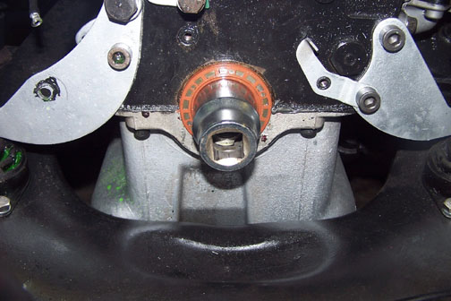
On the 220S engine, the crankshaft emerges at the front of the engine at the exact mating point for the oil pan and the engine block. My engine shop had used a sealant for a pan gasket when they put the oil pan on, which had pushed the oil pan down a little. Not a problem, but I was pretty sure my leak was around the edges of the seal, not at the sealing point on the crankshaft. With that in mind, I set out to install the new seal, but another problem emerged. The seal has to go on effectively backwards - and seals are designed to have the shaft installed from the front. When going on backwards, I couldn't get the seal cleanly onto the crankshaft without starting to roll an edge. The answer turned out to be the use of a 1 3/8" socket, well oiled, inserted into the seal the way the seal wanted it to go. Then, with the socket up against the crank, I slid the seal backwards onto the crankshaft and into place.
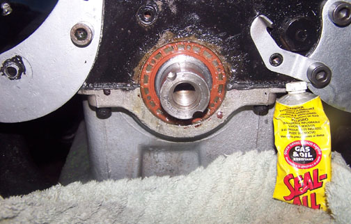
The final step on this exercise was to use a product called "Seal All," to seal the area around the edges of the seal and hopefully make the installation oil tight. It looked messy, but with everything back in place I started the engine and ran it another 20 minutes or so. During that time the leak was gone, so I'm happy for now. We'll see how long this holds, but it at least moves me towards a real shakedown run out on the road and the guy who turned me onto Seal All thinks it might well be a permanent solution. To my engine shop's credit, they had put some sealant around the edges of the seal, but apparently it wasn't quite enough. They don't see engines like this every day, and with the quantity and quality of work they do for me I'm happy to simply say "things happen sometimes."
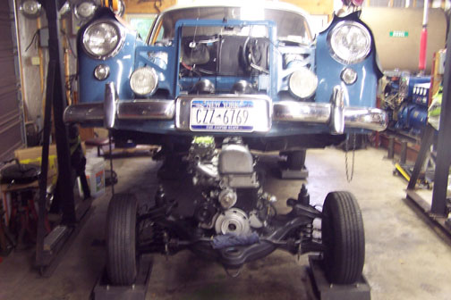
After the run-in period I changed the oil and filter, and began to see if I could get some of the fierceness in the Hydrak mechanical clutch to go away. I was in the process of doing that when the clutch simply stopped re-engaging, or so it seemed. After playing with my control valve, and actually getting a second one, it turned out that the mechanical clutch just wasn't doing what it was supposed to do. It was fully engaged, but, using the Hydrak servo, I couldn't disengage it enough to get a clean shift, and as best I can tell the servo is delivering full travel. With a great deal of reluctance, I pulled the engine back out of the car so we could get to the clutch and see what the problem was.
What I know for sure is that the clutch presently requires more displacement to disengage than the servo can deliver at full travel. Beyond that, it's still a mystery. The clutch shop is hanging with me though, and we'll get this figured out. Rather than speculate here on what the problem might be, I'll do another (hopefully final) update once I know the actual problem and solution. It shouldn't be too long. I'm on a mission to get this sorted out and back together pretty soon. That's the plan.
Final Installment / Conclusion / October 11, 2014
It took a little effort, but we managed to figure out and correct the mechanical clutch. The issue turned out to be the positioning, or height, of the release lever pivots. Contrary to my previous experience, where the clutch cover and pressure plate assembly are one unit with everything fixed in place, the mechanical clutch on this car uses three release levers, connected to a release hub, to haul the pressure plate back, and disengage the clutch.
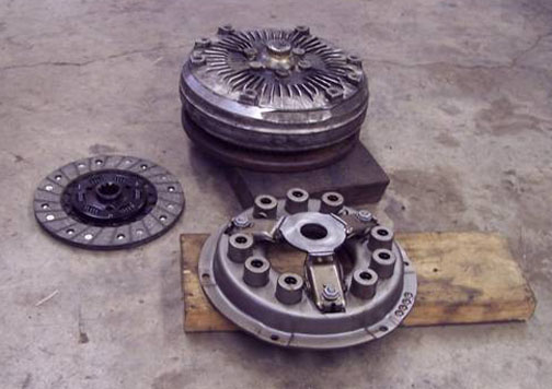
The height of the release lever pivot points, fixed by the studs and nuts/washers out near the end of each lever, determines the height of the release hub, in addition to the amount of travel needed to achieve disengagement. What had happened was that the shop had set the clutch up for use with a manual clutch pedal, which can produce almost three inches of travel. The Hydrak servo, on the other hand, produces about an inch and a half of travel on a good day. What we needed to do was raise the pivot points for the release levers to back the release hub as far away from the cover as we could, and additionally minimize the amount of travel needed for disengagement. Once we figured that out and made the adjustments, we put the clutch and transmission back on the engine, still out of the car, used a cheater pipe to operate the throwout lever on the side of the bell housing, and verified that we were getting disengagement in the right amount of rotation. With fingers crossed we put everything back together, raised the car and slid the engine back into position, and after lowering the car onto the subframe bolted everything back up.
Stilll, there was a little clutch drag, even after I checked and adjusted the free play. I'd noticed, though that because the clutch had been assembled for some time, a little bit of the disc lining was stuck to the pressure plate. My sense was that this was the source of the drag, i.e. the effective thickness of the disc was larger than original. To fix that, I put the car in gear, stood on the brake pedal, released the clutch using the shift lever and rev'd the engine. It didn't take long. That did the trick, and the clutch has disengaged cleanly since then. I did one more minor adjustment on the clutch free play, and I think we're in good shape there.
With the clutch finally working as intended, I drove the car over to my local guy who also does alignments, among other things, and had him put the front end in order. He also passed the car for its required New York State Inspection, making the car legal to drive anywhere in the state. Then, I actually test drove the car for a while. There was a little pull to the right on braking, and fair enough since all I'd done was make sure the cylinders held fluid. Otherwise, the leading indicators were good. With that in mind, I filled the gas tank all the way. Right about then, I realized that there were some small holes still in the tank near the top, where the tank liner was supposed to hold gas in. Unfortunately, there was one hole that was now putting a steady stream of gas on the floor. It will, of course ever be thus.
The tank had to come back out. Unfortunately, before it came out it still had around 16 gallons of premium in it. Fortunately, the drain plug was still free, so I drained the tank into some old cat litter pails, blew as much of the fumes out as I could and pulled the tank out. Asking around the area for solutions, I found an external sealer from Northern Chemical called Exo-coat.
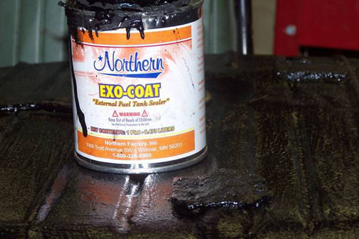
Three coats on the top of the tank, two on the bottom and particular attention to the seams, and I put the tank back in. We filtered the gas back into the tank through cheesecloth, filled the tank the rest of the way, and we're "good so far."
My local guy pointed out that gear lube was leaking from the axle seals on the right side, so before the run down to the Vintage Festival at Watkins Glen, I replaced both seals on that side. Time was getting short, though, since the seals didn't arrive until the Tuesday after Labor Day, and I needed the car online by Friday. That Wednesday, though, I finished up the seal replacement and got the car on the road. I put close to 300 miles on the car in the next two days - showing it to the shops that contributed so much, running down to Canandaigua for the heck of it, and so on. Everything looked good, so on Friday morning we headed for Watkins Glen. We did get there, and had a great time.
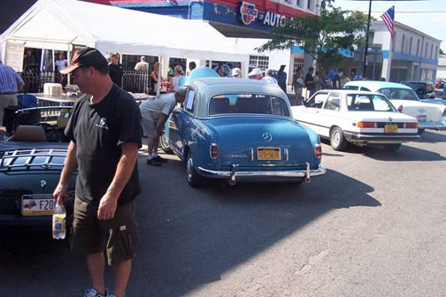
Here's the car in Watkins Glen on Franklin Street, with admirers in attendance.
There's much more I could say about the Vintage Festival this year, but long story short we managed to shake down a few more issues once we got the car out for a long run. The hydraulic cylinder on the brake booster turned out to be leaking, but it was going back into the booster and then through the engine. That was an issue. Once we made it home, the booster came out and went down to Virginia to get rebuilt and the cylinder sleeved. In addition, I'm pretty sure I didn't get the nut that retains the right rear wheel bearing on the axle tight enough, and as a result the lock tab holding the nut in place sheared off, leaving a big ding in the lock plate. With the nut no longer held in place, though, the nut backed off and the axle came loose. At that point I called for the flatbed. There are days, and then there are days.
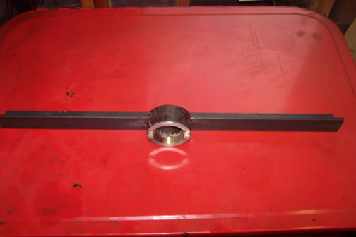
The right rear wheel bearing had been a little noisy - there was one rough spot in it, as it turned out, so I ordered a new bearing, new seals for both sides just because, and in addition new nuts and lock plates. My local fab-weld shop came through again, and made a tool that nicely envelops the retainer nuts, and can be used to turn the nuts down really tight.
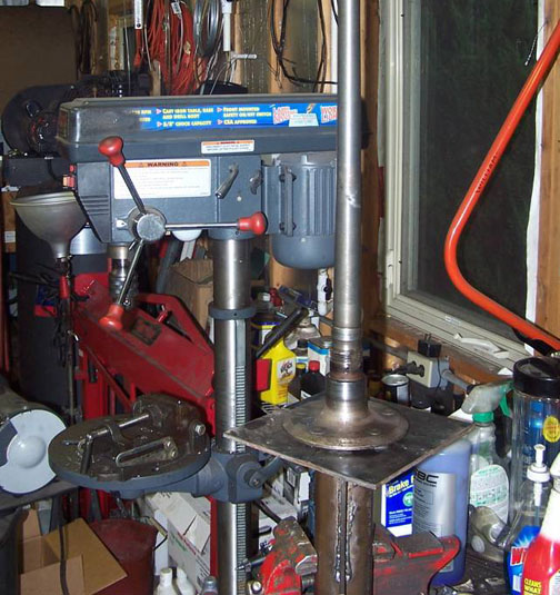
With the tool in hand, I used the flange plates I'd built to help move the car around during earlier phases of the refresh to now hold each axle in place in the vice so I could work at waist height.
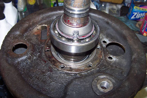
And finally I turned down the nuts, used a little red thread locker and hammered up the lock tabs. It's doubtful that I'll have another issue here. Also, with the axles and rear brakes out of the car I freed up one handbrake cable pulley and replaced the other, and installed a new rear handbrake cable. The old one was showing wear on one side, and I figured it was one of those "while we're here" situations.
To be sure the car was really solid this time, I ran it down to Watkins Glen for lunch one day, did a lap of the old course, and came home. No drips, no leaks, no errors. Plus, with the booster rebuilt the brakes are better than I think they've ever been. I suspect that booster cylinder had been leaking for quite some time. Finally, after that run, I changed out the oil to 20-50 and torqued the head. It looks as though I'll need to make another tool to allow me to roll the engine over so I can check the valve lash, but I think I'll shoot for spring 2015 to get that done. I have about 750 miles on the engine now, and with the head torqued it's getting much closer to that silky smooth six that I remember. We should be at a little over 1,000 by the time I lay the car up for winter, and I can design and make a tool over the winter. There's one valve that sounds like the clearance is a tich big, but it's not awful, and I can live with it for now.
I also fooled around with the Hydrak clutch engagement speed, and finally settled for a fairly brisk engagement rate. It's still a little jerky going into gear at a full stop, but the upshifts are crisp and the car's much more fun to drive that way. I also elected to disconnect the wiring from the rear axle switch for the Hydrak, since its intended use is to retard the clutch engagement speed on a downshift. In my mind, all that does is slip the clutch more, and I routinely double clutch this car on downshifts anyway - just because I can. On a good day, I can hit a really smooth and quick downshift. Then, there are other days, but practice improves the process. I'll just need to drive the car more. I don't view that as a punishment. Everything is still there, but I like the simplified design better.
So - after five years off the road, three years in restoration, or more correctly an "electrical and mechanical refresh" I've got my car back - or rather my father's car, as good or better than when he owned it.
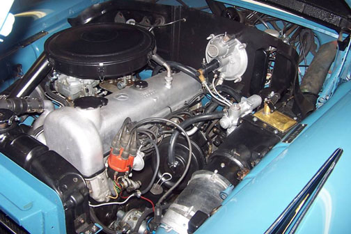
Here's a final shot of the engine room with the booster rebuilt and all the paintwork touched up.
I'd like to take a minute and publicly recognize some of the shops and suppliers that made major contributions to this effort. I owe all of them a large debt of gratitude for their patience, understanding and help. They are...
• Best Canvas / Williamson, NY
• Carl's Auto Service / Marion, NY
• Engine Assembly / Rochester, NY
• Hadley's Fab Weld / Marion, NY
• Macedon Parts Plus / Macedon, NY
• Magnum Auto Parts / Palmyra, NY
• Mercedes-Benz Classic Center / Irvine, CA
• Niemoeller's Mercedes Vintage Car Parts / Mannheim, Germany
• North Star Auto Electric / Macedon, NY
• Ray's Radiator Service / Newark, NY
• Rochester Clutch and Brake / Rochester, NY
• Vintage Benz 1 / Shelton, WA
• White Post Restorations / White Post, VA
• World Upholstery and Trim / Santa Paula, CAIt's been a journey. Now the next phase begins – it's time to go driving. Fall has arrived in the Finger Lakes. What better way to enjoy it than doing some stately motoring in a newly refreshed 220S. Now that's really a plan.
Created: January 10, 2012 / Jeff Miller
© www.mbzponton.org
Return to the Ponton Workshop page
Return to the Mercedes Ponton page