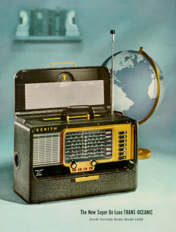
Photo 1. Zenith "Trans-Oceanic" (B600) Portable Shortwave Radio
Years Produced: 1959-1962
Zenith "Super De Luxe Trans-Oceanic Portable"
Model B600 / Chassis 6A40
Photo 1. Zenith "Trans-Oceanic" (B600) Portable Shortwave Radio
Years Produced: 1959-1962
Found in a Barn while Vacationing in Maine
The Trans-Oceanic 600 series was the final incarnation of a distinguished line of Zenith shortwave tube radios. It is historically significant because it was the last portable vacuum tube radio made in the USA It was produced from 1959-1962, and highly prized in its day.
Found this example on Thursday September 13, 2007, at "Super's Junkin Co." on Route 102 in Town Hill (Bar Harbor), Maine. The negotiated price was about $45, but that included a number of other items, so the exact price is impossible to determine.
The as-found condition could best be described as 90% intact, undamaged, but dusty with some serious surface grime and random mouse damage. The cabinet's brass colored trim was still in nice shape. I figured a little soap and water would go a long way. There were only two obvious physical problems: 1) a broken tuning dial cord, and 2) the red "ladder line" to the "Wave Magnet" antenna (for the broadcast band) showed signs of being nibbled by mice. Fortunately, there were no leaking batteries inside, but there were remnants of a mouse nest (copious sunflower seeds and recycled floor carpeting) in the battery compartment. I discovered more wire damage and a missing tube (50A1) when I got home. The mice were probably sad to see this thing disappear.
The evolutionary history of the Trans-Oceanic is quite interesting. There is a book called, "The Zenith Trans-Oceanic - The Royalty of Radios" which is an excellent chronicle. Authors: John H. Bryant, AIA and Harold N. Cones, Ph.D. See Essential Vintage Radio Books and Literature page for details.
Details
- Model: B600
- Chassis: 6A40
- Zenith Service Manual: Vol. 7 - Page 73
- Sam's Photofact: Set 381 - Folder 16
- Cabinet style: "Black Stag"
- Original cost: $139.95
- Dimensions: 17" x 8" x 11", Weight: 17 lbs. (without battery)
Tuning Range
Seven switchable bands provide the following coverage.Valve (tube) Lineup
- Standard Broadcast: 540 - 1600 kHz
- Weather Band: 4.0 - 9.0 MHz
- Weather Band: 2.0 - 4.0 MHZ
- 16 meter Band: 17.40 - 18.20 MHz
- 19 meter Band: 14.80 - 15.60 MHz
- 25 meter Band: 11.40 - 12.20 MHz
- 31 meter Band: 9.30 - 9.90 MHz
- 1U4 (RF amplifier)
- 1U4 (IF amplifier)
- 1L6 (Converter) (rare tube)
- 1U5 (Detector / AVC / First audio)
- 3V4 (Audio output)
- 50A1 (Current regulator / Ballast) (rare tube)
|
Table 1 Tube Testing Results and Replacement Prices |
|||
| Original Tube | Tube Type | Tested (AWA Museum) 30-sep-2007 | Replacement |
| 1U4 | RF amplifier | bad (Zenith tube) | 1U4 - $4.60 (tubesandmore.com) |
| 1U4 | IF amplifier | good (RCA tube) | N/A |
| 1L6 | converter | originally good (Sylvania tube) | N/A |
|
The 1L6 tested bad at Radio Daze during the final restoration phase (28-jun-2011 through 15-jul-2011). For reference: I provided a complete set of tubes when I dropped it off. The set only uses one 1L6 tube. The new in-the-box tube I provided was the 50A1 ballast tube that was ultimately installed in the radio. Radio Daze provided a New Old Stock (N.O.S.) 1L6 as well as returning the extremely weak 1L6 that came in with the set, and the extra tubes that came in with the set. |
$50 | ||
| 1U5 | detector / AVC / first audio | weak (Zenith tube) | 1U5 - $6.15 (tubesandmore.com) |
| 3V4 | audio output | bad (Sylvania tube) | 3V4 - $5.95 (tubesandmore.com) |
| 50A1 | current regulator / ballast | discovered missing 23-sep-2007 |
replacement tube: "D5TF30" Radio Daze $27.00 24-sep-2007 |
Mains
- 110-125 volt AC/DC 25-60Hz. A ballast adaptor was available as an extra cost option for 220 volt operation
Battery Power
- Zenith Z-985 (Combined 90 volt HT & 9 volt LT - rated for 150 hours service)
- 1.5 volt cell (Type Z1) for dial light
Wanted / Needed
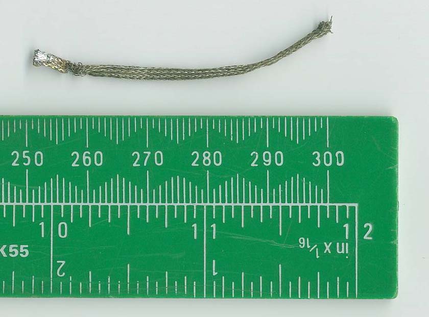
- Ground wire (braided, small gauge) for shortwave antenna shaft (can substitute solder wick for this purpose)
- Zenith Service Manual: Vol. 7 - Page 73
ReferencesImportant Schematic Information
- Overview: www.portabletubes.co.uk/portables/ztob600.htm
- Restoration: oak.cats.ohiou.edu/~postr/bapix/H500_2.htm
- Trans-Oceanic Gallery: www.antiqueradio.org/transoceanics.htm
- Trans-Oceanic Yahoo! Group: groups.yahoo.com/group/thetransoceanicfanatic
- AWA Yahoo! Group: Replacing the 50A1 ballast tube
The "Nostalgia Air" website (www.transoceanic.nostalgiaair.org) has an online .pdf schematic for the Trans-Oceanic model B600 with chassis 6A40, but it did not match what was in my Trans-Oceanic model B600 with chassis 6A40. Fortunately, the only thing I lost was the time spent making a capacitor shopping list. Even though the .pdf file annotations clearly indicate it was made for the model B600 with chassis 6A40, the component values on the .pdf file were not even close to the component values I found in my radio.My particular radio has "MODEL B600" printed on the inside of the rear cabinet door, and has "CHASSIS 6A40" printed on the rear of the chassis. So, I do not think the chassis has been swapped. I conclude that the online .pdf files are for another model, not the B600 with the 6A40 chassis.
- FOR REFERENCE ONLY: Bogus B600 schematic
- FOR REFERENCE ONLY: Bogus B600 capacitors
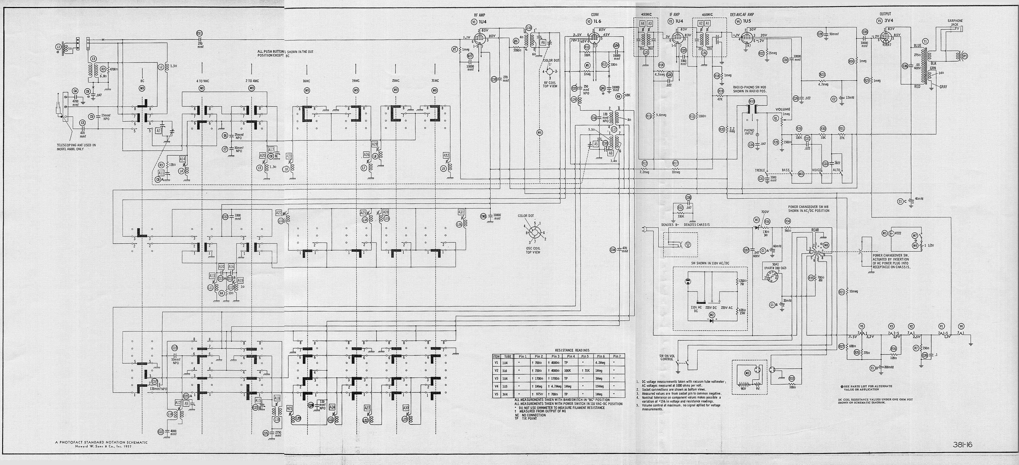
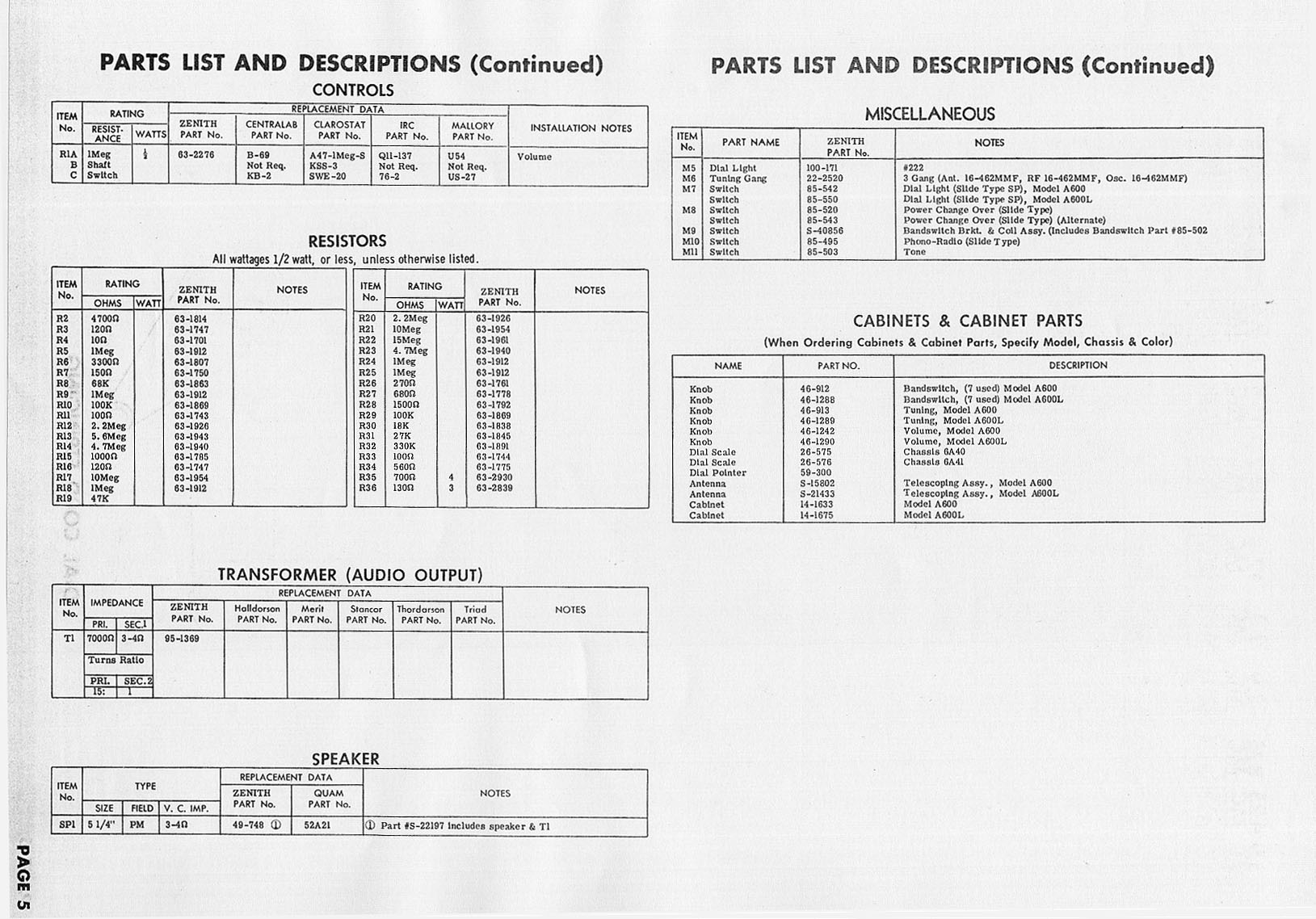
The correct schematic for the Zenith Trans-Oceanic B600 with chassis 6A40 can be found at many local public libraries under the name Sam's Photofact (Set 381 - Folder 16).
Sam's Photofact (Set 381 - Folder 16)Before you pay top price (eBay, online vendors, etc.) for photocopies of Sam's Photofact Sets, check the public library first. Many of them still have the old Sam's Photofact Sets readily available and will let you make copies for a nominal fee. A photocopy of a typical twelve-page Sam's Photofact Set will cost about $1.50 at the public library. Learn more
- Zenith Trans-Oceanic (valid for model B600 - chassis 6A40) Schematic
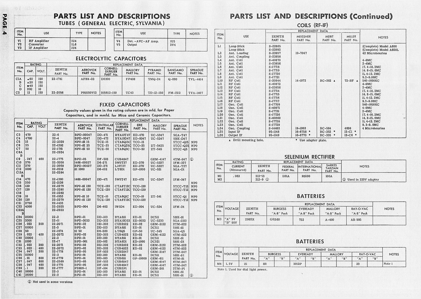
- Zenith Trans-Oceanic (valid for model B600 - chassis 6A40) Parts List (p. 1)
- Zenith Trans-Oceanic (valid for model B600 - chassis 6A40) Parts List (p. 2)
Restoration History
17-sep-2007 (Monday - vacation): Removed the plastic faceplate and cleaned all the plastic knobs, push-buttons and the tuning dial with a toothbrush and Murphy's Oil Soap. Vacuumed the sunflower seeds and scattered debris out of the cabinet. Used Kiwi black shoe polish paste on the "Black Stag" exterior of the Trans-Oceanic B600. Used Novus Plastic Polish #2, and Meguiar's Cleaner Liquid Wax on the Wave Magnet antenna housing. This initial cleaning took several hours but was well worth it.
19-sep-2007: Bought a photocopy of the Owner's Manual and Sam's Photofact set for the radio from eBay. The Photofact Set was not advertised as such, but that is what it was. Price was: $9.75 plus $3.00 shipping. The quality was not very good. The schematic part of the Sam's package was illegible on the smaller print. The larger photos were dark and not very good quality. I got rooked on this one.
19-sep-2007: Bought a "made-to-scale, high resolution replica" of the radio User's Guide. Price: $13.95 plus $4.95 shipping. Seller emailed and said they would not be able to ship until 24-sep-2007.
23-sep-2007 (Sunday): Removed the radio chassis from the cabinet. Used a 5/16" socket to remove the two screws from the underside of the radio cabinet. There are two access holes in the base of the Trans-Oceanic cabinet to get to the 5/16" screws. I discovered that the Type 50A1 (current limiting) tube was missing. Also discovered further minor wire damage by the mice. Will need to order some #20 AWG, cloth covered, stranded wire (black, red, white) to replace the frayed wires.
24-sep-2007 (Monday): Printed and studied the online .pdf schematics and made an inventory of the capacitors to prepare a shopping list. Discovered that the online .pdf file for the model B600 on the www.transoceanic.nostalgiaair.org site was not even close to what I found in the radio. The correct schematic for the Zenith Trans-Oceanic B600 with chassis 6A40 can be found at many local public libraries under the name Sam's Photofact (Set 381 - Folder 16).
24-sep-2007 (Monday): Purchased the missing 50A1 tube from Radio Daze. Price was $27.00. The replacement tube was actually a Type "D5TF30", which is supposed to be the same as the 50A1. Since New Old Stock (NOS) Type 50A1 tubes were ranging from $59.00 to $89.00 I was happy to get this D5TF30 for $27.00.
25-sep-2007 (Tuesday): Copied the Sam's Photofact (Set 381 - Folder 16) at the Rochester Public Library. Cost: $1.65.
30-sep-2007 (Sunday): Test tubes at the AWA Museum. Three bad tubes: 1U4, 1U5 (Zenith tube), 3V4.
30-sep-2007 (Sunday): Create table of replacement parts to be ordered
02-oct-2007 (Tuesday): Placed order for tubes, capacitors, cloth covered wire, dial cord, tension springs, etc. See table below. Ordered from AES (Antique Electronic Supply).
02-oct-2007 (Tuesday): Received dial cord in mail from Dave Thorn
04-oct-2007 (Thursday): Purchased ($10) original red Wave Magnet antenna wire (300 Ω balanced line) from a member of the Trans-Oceanic Yahoo! Group.
06-oct-2007 (Saturday): Received new Wave Magnet wire (red, 300 Ω, balanced line)
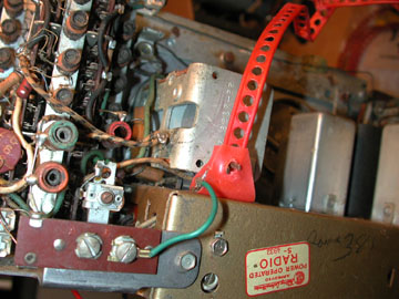
Photo 2. Some internal details, including the Wave Magnet wire
09-oct-2007 (Tuesday): I compared the new Wave Magnet wire (red, 300 Ω, balanced line) which came from another Trans-Oceanic B600, to the one in my project radio, and it did not have the same green wire going to the "G" terminal (see photo). Is the green ground wire correct and original? It is very conveniently located next to the "G" (ground) terminal of the chassis, but the solder on the green wire does not look factory original, and the schematic does not indicate a ground connection at "L1" (loopstick, a.k.a. Wave Magnet). I will assume it was added later, and not add a similar ground connection to the new balanced line.
10-oct-2007 (Wednesday): Stopped at Radio Daze on my way home from work to buy the capacitor value I forgot to order from AES. Radio Daze part number "C-MF.01-630." Value is: 0.01 µF, 630V, "orange drop" (needed 1, bought 2). Also got a five inch section of ground wire (braided, small gauge) for the telescoping shortwave Waverod antenna shaft. The ground wire was a little bit large, but it soldered into the pin just fine. Still need to solder the other end to the Waverod shaft. Screwed the telescoping Waverod antenna (seven-section, 52 inch [132 cm]) back into the Black Stag cabinet to keep it out of the way. Also soldered the new red, 300 Ω, balanced line into the Wave Magnet loop antenna assembly.
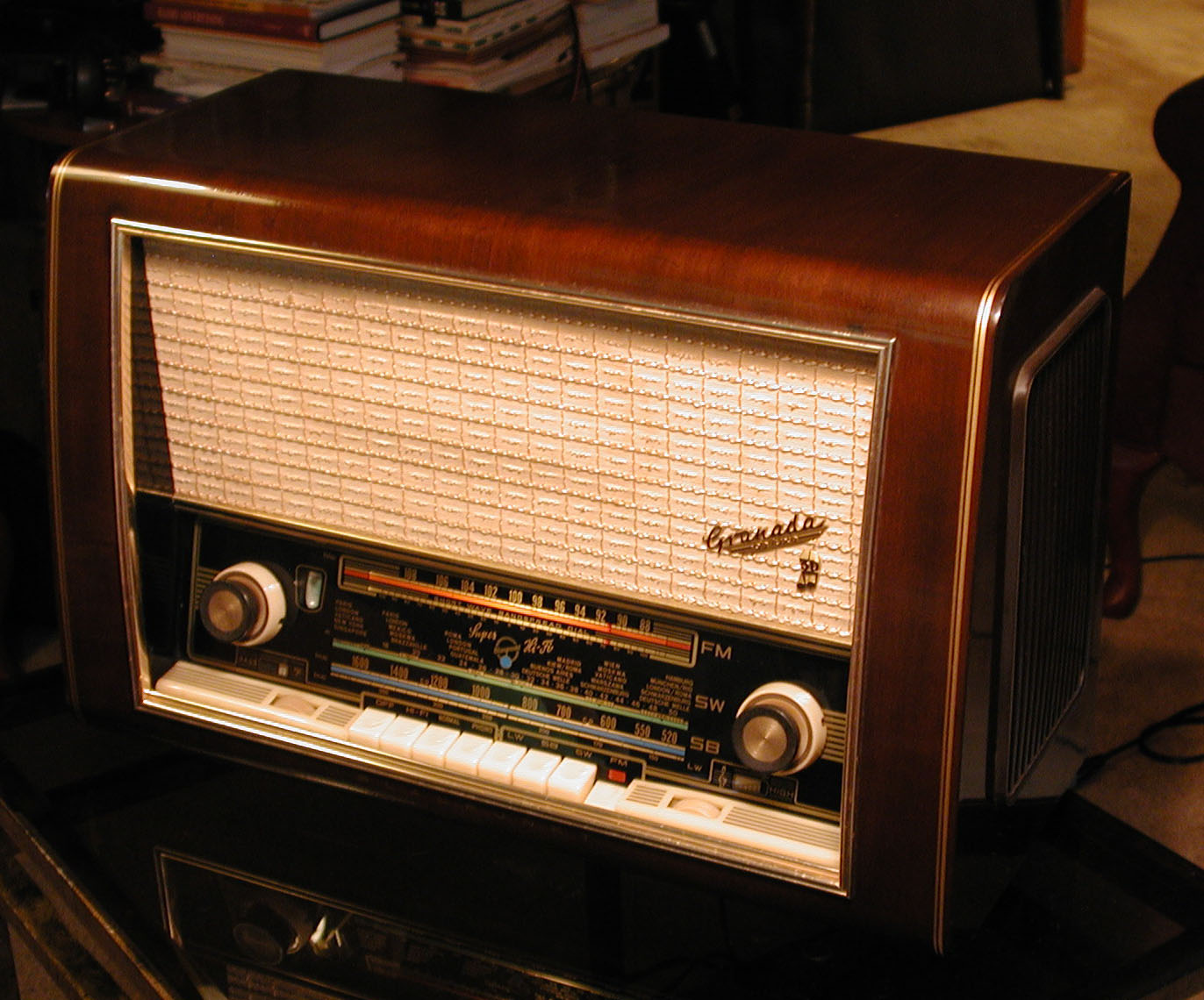
28-jun-2011 (Tuesday): Stopped at Radio Daze during a nice morning bike ride (I was working 11:00 a.m. - 8:00 p.m. that week) and noticed a handsome 1958 Blaupunkt "Granada deluxe 3D 2330" table-top radio and got thinking about making a trade; the Trans-Oceanic for the Blaupunkt. I inquired about making the trade and they were willing to allow $65.00 credit on the Zenith. The following day, I dropped off the Zenith to let them complete the restoration, and I also picked up the Blaupunkt. I was not ready to let the Trans-Oceanic go.
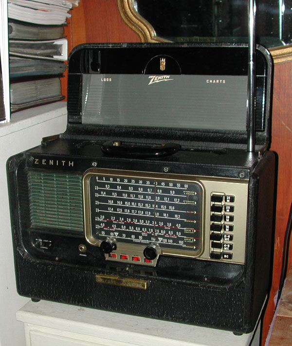
Photo 3. Maiden voyage – tuned to 7.415 MHz (WBCQ)
Photo: July 15, 2011 / Nikon Coolpix 990
15-jul-2011 (Friday): Picked up the radio in refurbished condition at Radio Daze. Sounded fantastic! The rare (and expensive) 1L6 tube had to be replaced. The technician at Radio Daze (Brian Sargeant) found it tested weak, although it tested good back in 2007. Price for new 1L6 was $50.00 (ouch!). The IF filter cans were also replaced, as well as the old capacitors. Mouse urine had infiltrated the thin mica capacitors. Dial cords had to be strung, and a few new wires were run around the inside due to the barn mice chewing on the originals.
Cost of this work was initially based on the number of tubes in the radio (six). They were charging about $25 per tube. Original quote was about $120, but it needed the 1L6 ($50) and some additional time and miscellaneous parts (each IF can was $10.95) due to the mouse damage. Total came to $177.90 (including a $20 discount). Total for parts (see elsewhere on this page) $65.83. Total for tubes (except the 1L6) was $44.05. Two reproduction knobs with gold inserts were $15. Grand total: $177.90 + $65.83 + $44.05 + $15.00 = $302.78.
20-jul-2011 (Wednesday): Was listening to the radio and it suddenly started to get a lot of static on the signal. Then the signal disappeared completely. It was the same for all AM stations. Dropped it off at Radio Daze on my way to work.
25-jul-2011 (Monday): Brian Sargeant (Radio Daze) e-mailed to say the IF can had been replaced. The previous one (he had just replaced it) had shorted. He said he had never had to replace IF cans on any Trans-Oceanic radios.
27-jul-2011 (Wednesday): The knobs (for the On-Off switch, and the tuning dial) did not have their original gold center trim. Ordered two black reproduction knobs (with gold center trim) from:
Alan Jesperson
gn4radios.com
Great Northern Antique Radios
5200 Bloomington Ave. S., Minneapolis, MN 55417
$5.00 each plus $5.00 shipping ($15 total)
He accepted Paypal to e-mail address: mte612 ]at[ aol.com
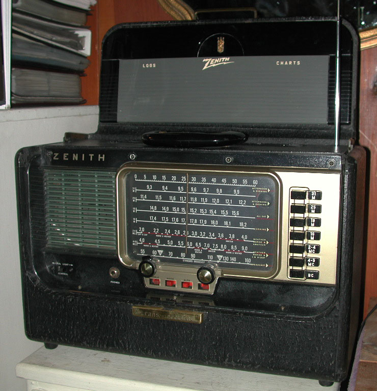
Photo 4. The new knobs arrived August 1, 2011 – making a nice difference
Photo: August 1, 2011 / Nikon Coolpix 990
19-jan-2016 (Tuesday): Made the trek to Brian Sargeant's QTH to troubleshoot a buzzing on the broadcast band. Unfortunately, he no longer worked at Radio Daze, which was only two miles from my shack. The buzzing obliterated the signal at 1040 kHz (WYSL), and varied in intensity up and down the dial.
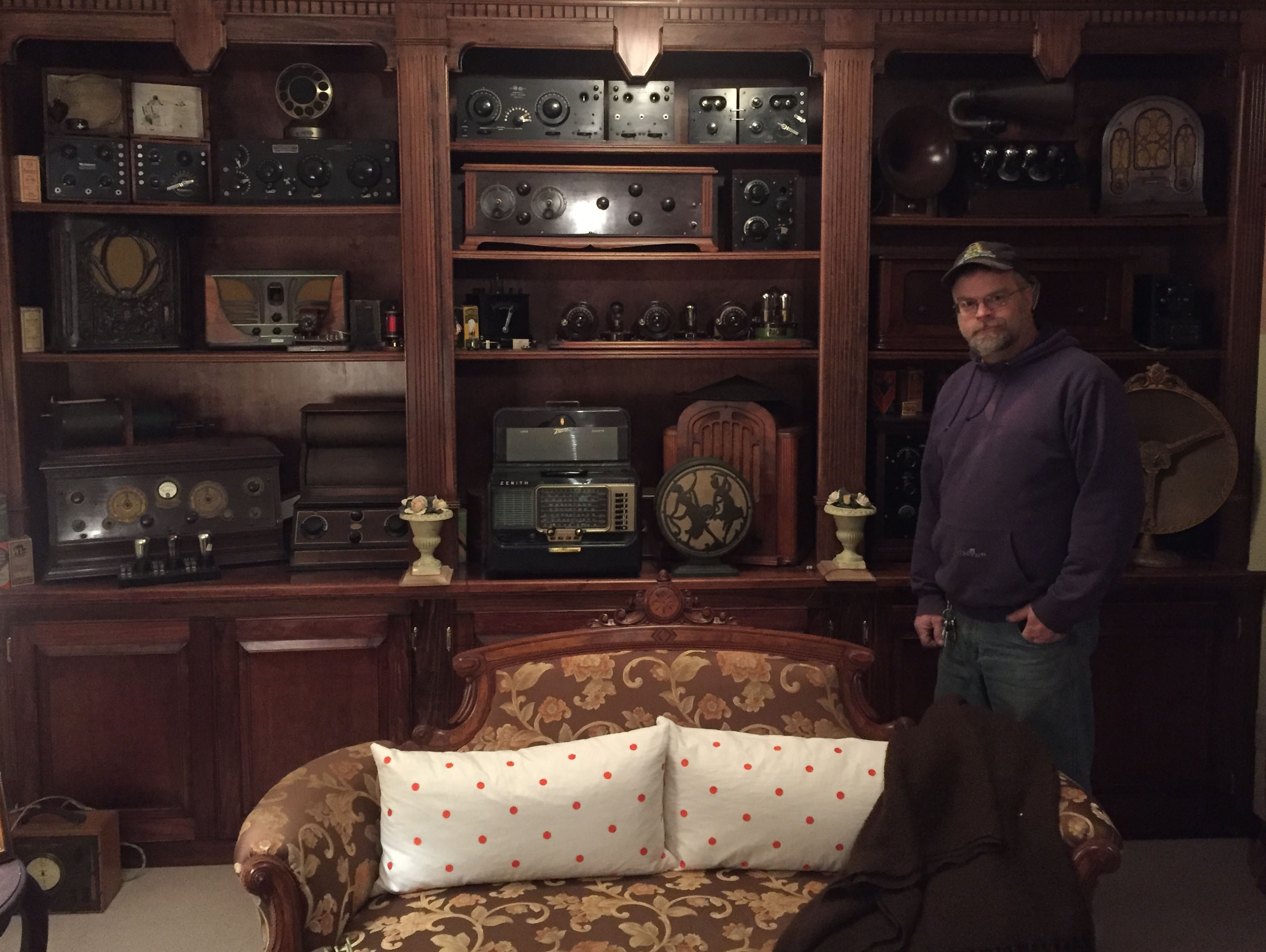
Photo 5. February 10, 2016 – Brian M. Sargeant (1961 - 2022) with my Zenith B600 on display in his parlor.
10-feb-2016 (Wednesday): Picked up the B600 at Brian's place where he was unable to duplicate the problem! Before describing his impressive antique radio collection, I got a look at his classic cars, which included a mammoth 1960 Buick four-door in the midst of a full rotisserie restoration, and a fully restored, 1968 GT/CS a.k.a. "California Special" Mustang – one of only 4,118 built. Once the Trans-Oceanic was back home, the buzzing interference was gone. Nothing seemed different on the circuits, so it was unclear what had caused the noise.
12-feb-2016 (Friday): Finally determined the source of the buzzing to be an FS-4 fluorescent starter on an aquarium light. Replaced the starter, and updated Brian. There is probably a lesson to be learned here somewhere.
Replacement Parts
|
Table 2 Replacement Parts for Zenith Trans-Oceanic B600 Compiled: 30-sep-2007 through 02-oct-2007. Placed order: 02-oct-2007 Vendor: "AES" (Antique Electronic Supply - www.tubesandmore.com) |
|||||||||
| Schematic part number | Original component and composition | Value (original) | Value (replacement) |
Composition of new part | Vendor (Part number) | Price ($) | Quantity (actual) | Ordered | Total ($) |
| V1 | RF amplifier and/or IF amplifier (valve) | 1U4 | 1U4 | miniature glass vacuum tube | AES (1U4) | 4.60 | 2 | 1 (only one 1U4 valve tested bad) | 4.60 |
| V4 | detector / AVC / first audio (valve) | 1U5 | 1U5 | miniature glass vacuum tube | AES (1U5) | 6.15 | 1 | 1 | 6.15 |
| V5 | audio output (valve) | 3V4 | 3V4 | miniature glass vacuum tube | AES (3V4) | 5.95 | 1 | 1 | 5.95 |
| C1 | four-section electrolytic capacitor | A: 60 µF 150v, B: 20 µF 150v, C: 40 µF 150v, D:200 µF 150v | N/A | N/A | N/A | N/A | 1 | 0 | 0 |
| C2 | electrolytic capacitor | 12 µF 150v | 10 µF 160v (12 µF is not readily available) | axial lead electrolytic | AES (C-ET10-160) | 0.91 | 1 | 2 | 1.82 |
| C34 | paper capacitor | 0.047 µF 200v | 0.047 µF 600v | SBE 715P orange drop | AES (C-RD047-600) | 0.97 | 1 | 2 | 1.94 |
| C9, C38 | paper capacitor | 0.047 µF 400v | 0.047 µF 600v | SBE 715P orange drop | AES (C-RD047-600) | 0.97 | 2 | 4 | 3.88 |
| C37 | paper capacitor | 0.047 µF 600v | 0.047 µF 600v | SBE 715P orange drop | AES (C-RD047-600) | 0.97 | 1 | 2 | 1.94 |
| C26, C32 | paper capacitor | 0.022 µF 200v | 0.022 µF 600v | SBE 715P orange drop | AES (C-RD022-600) | 0.87 | 2 | 4 | 3.48 |
| C29, C33 | paper capacitor | 0.022 µF 400v | 0.022 µF 600v | SBE 715P orange drop | AES (C-RD022-600) | 0.87 | 2 | 4 | 3.48 |
| C39 | paper capacitor | 0.1 µF 200v | 0.1 µF 600v | SBE 715P orange drop | AES (C-RD1-600) | 1.16 | 1 | 2 | 2.32 |
| C36 | paper capacitor | 0.01 µF 600v | 0.01 µF 630v | SBE 715P orange drop | Radio Daze (C-MF.01-630) | 0.31 | 1 | 2 | 0.62 |
| M1 | selenium rectifier | current (measured) 0.63 | 1N4005 (1A, 600v) diode | silicon | AES (P-Q1N4005) | 0.25 | 1 | 2 | 0.50 |
| M2 | selenium rectifier | used with 220v adapter (if applicable) | 1N4005 (1A, 600v) diode | silicon | AES (P-Q1N4005) | 0.25 | 1 | 2 | 0.50 |
| R36 | dropping resistor for "M1" rectifier | 130 Ω, 3w | 150 Ω, 5w power resistor to compensate for efficiency of new "M1" silicon diode rectifier | wire wound | AES (R-Q150) | 0.70 | 1 | 2 | 1.40 |
| N/A | dial cord | diameter unknown | 0.028" dia. | cloth | AES (S-M75) | 1.00 per foot | length unknown | 6 feet | 6.00 |
| N/A | tension springs for dial cord | original size unknown | new size unknown | metal | AES (S-H400) | 1.00 per 10-pack | 3 | 1 (package of 10) | 1.00 |
| N/A | wire (red) | red #20 AWG stranded, cloth covered | #20 AWG stranded, cloth covered | #20 AWG stranded, cloth covered | AES (S-W705L-25) | 6.75 per 25' spool | 1 foot (approx.) | 1 (25' spool) | 6.75 |
| N/A | wire (white) | white #20 AWG stranded, cloth covered | #20 AWG stranded, cloth covered | #20 AWG stranded, cloth covered | AES (S-W709L-25) | 6.75 per 25' spool | 1 foot (approx.) | 1 (25' spool) | 6.75 |
| N/A | wire (black) | black #20 AWG stranded, cloth covered | #20 AWG stranded, cloth covered | #20 AWG stranded, cloth covered | AES (S-W704L-25) | 6.75 per 25' spool | 1 foot (approx.) | 1 (25' spool) | 6.75 |
| Final Order Vendor (Part Number) (Quantity) (Date Received): AES (1U4) (1) (rec'd. 09-oct-2007) AES (1U5) (1) (rec'd. 09-oct-2007) AES (3V4) (1) (rec'd. 09-oct-2007) AES (C-ET10-160) (2) (rec'd. 09-oct-2007) AES (C-RD047-600) (8) (rec'd. 09-oct-2007) AES (C-RD022-600) (8) (rec'd. 09-oct-2007) AES (C-RD1-600) (2) (rec'd. 09-oct-2007) Radio Daze (C-MF.01-630) (2) (rec'd. 10-oct-2007) AES (P-Q1N4005) (4) (rec'd. 09-oct-2007) AES (R-Q150) (2) (rec'd. 09-oct-2007) AES (S-M75) (6 feet) (rec'd. 09-oct-2007) AES (S-H400) (1) (rec'd. 09-oct-2007) AES (S-W705L-25) (1) (rec'd. 09-oct-2007) AES (S-W709L-25) (1) (rec'd. 09-oct-2007) AES (S-W704L-25) (1) (rec'd. 09-oct-2007) |
Grand Total: 65.83 (shipping not included) | ||||||||
Replacement Parts (Questions / Answers)
Being a relative newcomer to vintage radio restoration, I have not amassed a large inventory of spare parts. When I take on a new project, I begin by making a shopping list so everything will be available when the work starts. You start baking a cake with all of the ingredients in the kitchen, and the same holds true for vintage radio projects. Most of the information gathering is straight forward. Scrutinize the schematic, and cross reference it to the parts list (when available) and note any components that may be subject to failure due to the advanced age of the set. These include paper capacitors, electrolytic capacitors, and the selenium rectifier. A few resistors may be needed, and also test the vacuum tubes. So far, this process boils down to good organizational skills. However, there are usually a few things that need clarification before the parts order is placed. Most of the questions involve "best practices" in the realm of vintage radio restoration, or perhaps a bit of radio theory. Each project is different, and provides an opportunity to learn more. This section includes some questions and answers pertinent to the Zenith "Trans-Oceanic" Model B600.
Question 01 (01-oct-2007)
Selenium Rectifier "M1" and "M2"
Can I substitute a Type 583-BR34 (3A 400v) silicon bridge rectifier for the selenium rectifier ("M1" and "M2" in the schematic)? According to the schematic, M2 is only used when the 220v adapter is fitted. I am not sure if M1 and M2 are part of a single selenium rectifier or not. Maybe all selenium rectifiers had four leads, and to replicate one, I would need four diodes, but I just do not know that for certain.
Or perhaps I should use two separate 1N4005 (1A, 600v) silicon diodes. One for M1 and one for M2 (if applicable). The reason I ask is because it looks like the selenium rectifier (M1 and M2) are two separate diodes in the schematic. They appear to be half wave rectifiers. They are not drawn as a four diode "bridge" (full wave rectifier) as found in the Grundig "2066 PX" radio schematic.
AnswerUse separate diodes. These diodes are individual units in the set. You may not even have the 220 volt adaptor. It plugs into to the top of the chassis and looks like a caged square box.
Question 02 (01-oct-2007)Does A Replacement Diode Need A Dropping Resistor?
To compensate for the efficiency of a new silicon bridge (or diodes), a "dropping" resistor of about 100 Ω / 5W would be required. Would new silicon diodes need a dropping resistor too?
Answer
The new diodes (individual or bridge) have a silicon junction that will drop 0.7 volts. The selenium rectifiers dropped from 10 to 40 volts depending on the diode and current flowing through. You should use a series resistor to drop the extra volts. Set the series resistor R36 (originally 130 Ω 3w) (after "M1" on schematic) up to about 150 Ω and re-check your B+ (plate voltage relative to the cathode). Adjust the resistance to get B+ correct. Check your line voltage first. Somewhere in the Sam's Photofact Set it will specify the line voltage. If your line is not on the specified test voltage, then mentally compensate the B+ in your head. The schematic shows R36 as a 3w resistor. So, a 3 watt minimum for the replacement is fine. To be sure, measure the voltage drop across your final value resistor and use Ohm's law to figure the actual power (in watts) (P = E² / R) and double it for safety. The notes on the schematic say +/- 15% on the voltages.
If you have the 220 volt adaptor, set the unlabeled resistor (620 Ω 15 w) (shown after "M2" in the schematic) after setting the new R36 value. Otherwise, leave the unlabeled resistor alone.
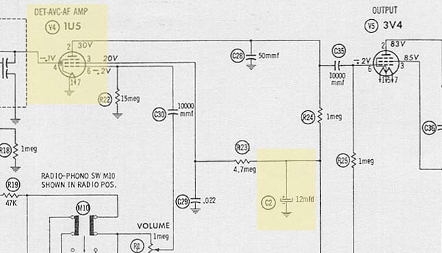
Question 03 (01-oct-2007)Replacing Capacitor "C2" (12µF, 150v, electrolytic)
I was trying to find a suitable replacement for "C2" (12µF, 150v, electrolytic). Radio Daze and AES (Antique Electronic Supply) did not carry the exact value, and the Mouser web page returned a lot of hits, but when I drilled down into the .pdf files, the only 12 µF 150 v electrolytic capacitor was about $26.00. Mouser e-mailed me and verified this was true.
Replacement capacitors should be the exact same capacitance value (12µF in this case) and the same or higher WVDC (working voltage). So, I think I could use two 6 µF electrolytic capacitors in parallel to add up to 12 µF. Or I could also use two 24 µF electrolytic capacitors in series to get the 12 µF value. Unfortunately, 6 µF and 24 µF are not standard values either.
AnswerC2 - Just go UP to the next commercially available/convenient µF value (15µF). No problem. Just do not go LOWER on the VOLTAGE rating (WVDC) or POOF! Capacitor C2 is for the the AVC (automatic volume control). If it is significantly larger (say, 24 µF) it will slow down the AVC response. You would only notice this when tuning across loud strong stations. You would hear a slow return to loudness of the static between stations. A little smaller (10 µF) should not be noticeable.
Question 04 (25-may-2009)
Where Can I Get The Battery Pack?
Answer
Website with information on the battery pack: www.zenithtrans-oceanic.portabletubes.co.uk/power.htm
Acknowledgements
The restoration of this radio could not have been accomplished without the support of various people and resources. Their contributions included advice, parts, and encouragement, and made it much easier to be successful. Thanks to: Paul Pinyot (Pennsylvania), Dave Thorn (Penn Yan, NY - dial cord), Antique Electronic Supply (AES), Dennis D'Amico (original, red, Wave Magnet antenna wire), and ultimate kudos go to to Brian Sargeant (Radio Daze) who transformed this former mouse apartment into a beautiful, working, classic radio.
