Douglas P. Broome / douglas.broome@verizon.net / McLean, Virginia USA
If you are reading this article because the title attracted you, STOP NOW! Return immediately to your Mercedes-Benz Ponton and examine the wiring between the generator and the voltage regulator. Determine its condition. Are there three wires flopping around with no sheathing around the group? Have individual wires previously been repaired? Is the insulation casing cracked on one or more of the individual wires? Are bare strands exposed? Has plastic electrical tape been used to cover bare wire? Have replacement connectors been crimped on? Are the connection points rusted, corroded, crudded, etc., possibly inhibiting good electrical contact? After your examination, return to this article.
These wires handle more current than any other wire in your Ponton save the battery cables. They take, additionally, a greater constant beating through vibration, flexing, and contamination than any others. The years take their toll perhaps more here than anywhere.
If you find signs of deterioration, which you may do unless recently renewed, you have a serious potential threat. Fire, for one thing: they are not far from the carburetor(s) and the fuel feed. A broken wire shorting across the wrong connector, destroying the regulator or generator, is another. You should seriously consider installing new wires before doing anything else and before taking your next drive. This article describes what I did to fashion a new harness. Note that I am not presenting a way of making a harness that is made of original-type materials. I saw no real purpose in paying for originality, as I wanted functionality and safety that looked generally appropriate. Also I like the satisfaction of doing my own job. I leave purity for the authenticists, although later in the article I identify some sources for this purpose.
The three stranded wires were originally sheathed in a single cloth cross-hatched (braided?) harness. The individual wires themselves were sheathed in some sort of lacquer-covered cloth insulation. When Mercedes converted from cloth/lacquer-covered wire to plastic in the mid-1950s for most wiring, for reasons that are now unclear they continued to use lacquered cloth on the most important, unfused parts of the wiring system; e.g. generator harness, regulator to starter, to light switch, to dimmer switch, etc. These wires should be checked carefully.
The Service Manual Model 190, 190b (p. 54-4) depicts the original harness, and it applies to all Ponton gasoline models. It identifies the wire colors and gives their thickness in millimeters. In the following table I present them converted to American Wire Gauge (AWG) format rounded upwards to the nearest standard size available in the United States:
- black 14
- brown 12
- red 10
These AWG equivalents are slightly larger than the original millimeter wires. This provides an added margin of capacity.
Note that one never uses solid-core wire. Only stranded wire is appropriate for automotive purposes because of flexing requirements. Normally there are 19 strands in each wire regardless of gauge.
First, disconnect the battery. Then turn to the generator wires. When looking at the wiring, one finds that the nut on one of the generator posts will not come all the way off. It spins around at the end, so don’t try to force it off thinking it is being stubborn. From this post the black wire connects to a screw connector on the voltage regulator. That screw will loosen most of the way and spin, but it will not come all the way out. This too is deliberate; so don’t try to force it. Note the hook-type connectors on the black wire. This arrangement is purposeful so that only the black wire can connect to these two locations. Make a drawing of which color wire goes between which points. Remove the old harness. Save it for reference.
Don’t lose the nuts, washers, or screws, and note where they go. Remove the ground strap on the front side (direction of travel) of the regulator. Clean and burnish with a wire brush all the screws, nuts, washers, posts, and screw holes that you can. I used a Dremel-type tool with the wire brush. One with an extension cable makes the job easier, but it is not essential. Clean off the flat areas around the screw holes on the regulator, generator, and ground strap. I happened to have a #6 metric tap that cleaned out the screw hole where the ground strap connects to the frame (the larger of the two holes for the strap). You will be surprised how much rust, corrosion, and crud there is at all these locations. Conductivity may have been compromised somewhere, so you want to clean it all well. For that reason when I had all the wires to the voltage regulator disconnected, I removed it and cleaned up all exterior areas. I wire brushed the screws and fittings where the regulator connected to the chassis in order to facilitate grounding. I cleaned and repainted the black cover before reinstalling the regulator.
From a local home center I bought two feet each of stranded red #10 AWG wire, brown #12 AWG wire, and black #14 AWG wire.[1] On the casing it says that it is resistant to oil and gasoline. From a local electronic parts store I bought heat shrink tubing of relevant diameters. I got ring and hook connectors appropriate to the wire gauges and for no. 10 posts. One ring size works for the red #10 AWG wire and another for the brown #12 AWG wire. The hook is for the black #14 AWG wire.
To fashion the harness I did the following: I slipped the wires into two quarter-inch-diameter heat shrink tubes, each cut to four inches in length. The fit is snug but not too tight to work. I had butted them up to each other to make a length of eight inches. At this point note the natural curvature of the wires that comes from being on a spool. No reason to try to fight this, so plan to install the ring connectors with this curvature in mind with respect to their eventual connections. That way you work with the wires, not fight them. This point is not essential.
On the end you plan to connect to the generator, have the red and black wires extend out of the shrink tubes about two inches. Make the brown wire extend about three inches.
On the end going to the voltage regulator cut the black wire so that it extends two inches from the end of the shrink tube. Cut the red wire at three inches from the tube’s end. Cut the brown wire at four inches. Put the rest of the wires to the side in case you need to do the job again.
Then look at the new ring and hook connectors. If they have insulators, remove them. You want to be able to get heat shrink tube over their crimped/soldered ends later. Set two of the largest connectors aside for the red wire and two of the smaller ring connectors aside for the brown wire. Set the hook connectors aside for the black wire.
Strip the insulation of each end of the wires appropriate to inserting them into the connectors, about one-fourth inch. Be sure not to cut any of the strands. Then cut six one-inch lengths of the smaller-size heat shrink tube and slip them loosely over each wire end down to where they can go no further. Massage solder flux into the exposed wire ends. Fit on the appropriate connector on one end of the harness. In doing this take account of the orientation I mentioned above. Once you are satisfied, crimp the connector onto the wire, using a regular electric wire-crimping tool. After the three connectors are crimped on, insert solder into them using a soldering iron. Be careful not to melt any of the adjacent casings on the wires. Check that each solder job is clean and good.
Apply heat to the eight-inch length (actually, two four-inch lengths) of heat tubing over the wires to fix it into place. Then, one by one, pull up each one-inch length over the joint section of the connectors you have already soldered. Be sure to have a small lip of tubing extend over the joint so that it helps keep the tubing piece from slipping off the connector and back onto the wire casing. Heat shrink them into place. I used a paint stripper heat gun, but a hair dryer should do.
Then cut a piece of three-eights-inch-diameter heat shrink tubing into a length of eight-plus inches. Insert the harness into this. Do not heat shrink this outer casing as it will remain as a loose casing. (An alternative is cloth friction tape would around the wires tightly).
Install the connectors, crimp and solder them, as above, on the opposite ends of the wires. Pull up the heat shrink tube over the connector ends and heat to shrink fit.
Install the harness and shape it so as to put the least strain on the six connectors and on the junctions between the wires and the ring connector pieces. Reinstall the ground strap at the point where it connects to the chassis (it will already be fastened with the brown wire at the regulator). Verify one last time against the drawing you made at the outset that the wires are connected correctly.
"Ooh" and "Aah" at your handiwork appreciatively. Feel good! Feel virtuous! Reconnect the battery and start the car. If there are no problems with the harness, shut the car down and go have a beer. Toss the old harness. You did the whole job for little money exclusive of tools. You could have bought a braided Mercedes harness (180-540-00-08) for $20.00 list or one from Rhode Island Wiring Service for about $20.00, both plus shipping. Half way through the beer you will contemplate whether the effort was worth your while.
Two other wires lead from the voltage regulator: a blue 1-mm (#16 AWG) wire to the generator light at the dash and a red 2.5-mm (#12 AWG) wire to the starter. One should verify their condition at this time and make appropriate repairs. Note they lie under the passenger side heater box and blower housing, so removing the latter may make this easier.
Below are some supplemental considerations for those eager for more information. For purists who require an original-type exterior braid on the harness instead of loose heat shrink tube, some kind is available at discount auto parts stores and electronic parts vendors. Antique automobile wiring shops can do the job properly. One place that will put on braid on your self-done harness is:
Anyone who does the generator harness may get so charged up - bad pun intended - that he decides to undertake other wiring harnesses on their Mercedes-Benz Ponton, even the whole lot. This may not be all that difficult. An excellent article for DIYers (Do It Yourself) is available at pp. 21-24 of Volume 25, No. 3, October 2000, Issue No. 221, of Skinned Knuckles. Their website is: skinnedknuckles.net. Alternatively, Rhode Island Wiring Service’s online catalogue www.riwire.com lists a number of Mercedes-Benz Ponton harnesses.
Harnesses Unlimited, Box 435, Wayne, PA 19087; phone: 610-688-3998. Cost is unknown. This place also sells wiring supplies, including connectors and wires with old-style casing.
Authentic antique-type wire and other items are also available from Lee Pedersen, 78 Taft Avenue, Lynbrook, NY 11563. Pedersen has an online catalogue at: www.enginads.com/pedersen/index.html.
Rhode Island Wiring Service; phone: 401-789-1955. Well known for good quality, but one will need to enquire about specific services (including braiding only) and parts.
Old-style wiring and supplies are also available from YnZ’s Yesterday’s Parts, 333 East Stuart Avenue, Redlands, CA 92374; phone: 909-798-1498.
A handy website for all sorts of electrical services and supplies vendors is the Classic Auto Mall. Search for their website with the internet search engine of your choice.
Finally, some sources suggest that, when doing generator harnesses, one should use wire with a more robust plastic/PVC insulation casing that is resistant to higher temperatures. I did not make much of a search to find any supplies, although perhaps this is what is sold as "primary wire" at auto parts stores. Given the considerable air flow in the generator area of the Pontons, I have to wonder if this is necessary especially since the AWG-standard wires used are larger than the original metric wires.
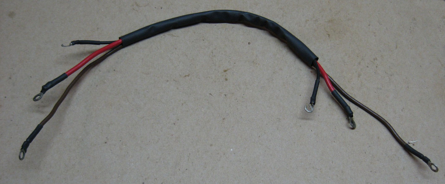
Figure 1. DIY version of a Mercedes-Benz Ponton generator wiring harness
Footnotes
[1] Get three feet (3') if you are a klutz, and fear screwing up the first effort. This is enough to do the job a second time.
Revision History
- Revision B / fixed broken links / January 14, 2018
- Revision A / added photo of wiring harness / February 6, 2017