Rebuilding Vintage Bosch Dynamo/Generator Regulators
Drew Ritland / Everett, Washington / dritland@frontier.com / 1954 Mercedes-Benz Type W186 300Introduction
Voltage regulators in the context of generator control are electromechanical devices designed to monitor and control the charge and discharge rate of a vehicle’s battery.
Other internal provisions may be in place for routing energy into the car's electrical system when no battery or a dysfunctional battery is present and providing an upper limit charge rate cut-out.
In the case of the Bosch systems used on vintage Mercedes-Benz vehicles, it controls the field current on the ground side of the field coil. This changes the strength of the magnetic field surrounding the rotor. In this way, output voltage (and hence charging current into the battery) can be controlled.
All of these tasks are accomplished with relays, resistors, contact points and 1930s ingenuity.
Options
Generic mechanical equivalents may be available on the open market. Many vintage auto enthusiasts shudder at altering mounting locations, wire re-routing and the original appearance of the engine bay. This would also preclude merely adopting one of the many "1-wire" alternator conversions generally available. The author is compelled to mention that the reliability, energy density and charge control provided by modern alternators is truly astounding.
We are left with trying to use salvaged Bosch regulators, or rare and expensive new-old-stock. In either situation you still have the same electromechanical regulation system which, by its very nature, can be kind of brutal to your battery chemistry due to inconsistent or non-ideal charge profiles.
Solid-State Options
Today, solid-state, fully electronic charger control is available.
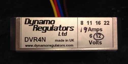
ElectroDynamic Solutions is our friend. Their product, the DVR4, can fit entirely within the housing of your original regulator, and conversion is simple. Accurate charge control is maintained over a wide RPM range.
The reader is highly encouraged to read the instructions and documentation presented by ElectroDynamic Solutions at the following links.
Note: as of July 2021, DVR4 was marketed and produced by ElectroDynamic Solutions at http://edsltd.ddns.net
The DVR4 product line can be found at http://edsltd.ddns.net/products2.html
Note: the author has no affiliation with this company other than being a satisfied customer.
Which Product to Use
The DVR4 is specifically designed for the type of generator in your vintage Mercedes-Benz. The Bosch "series field" style (the rotor output connects to one side of field, and the other side of the field is controlled by current to the chassis).
Stamped onto the side of your generator should be the output voltage and current rating. The DVR4 is available with many standard voltage and current settings. I elected to pay the extra £10 and get mine with a custom 19A rating to match the generator in my car. Just follow the drop-down menus in the order form.
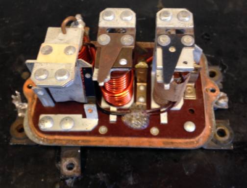
The Donor Regulator
My original regulator was still functional, and my generator was in good order. I elected to purchase a sacrificial Bosch regulator to convert. Had the conversion been unsuccessful, I could have returned to my original regulator.
The good news is that the donor does not need to function. It does not even need to be the same part number or ratings. The only requirement is that it has the correct outward physical appearance, mounting locations and dimensions. This allowed me to choose from a larger array of possible donors. Note that I was intent upon obtaining a regulator with “Bosch” in a cursive script instead of block letters, so some searching was still required.
Step 1
Remove the outside cover. This is a good time to refinish the cover and replace the decals.
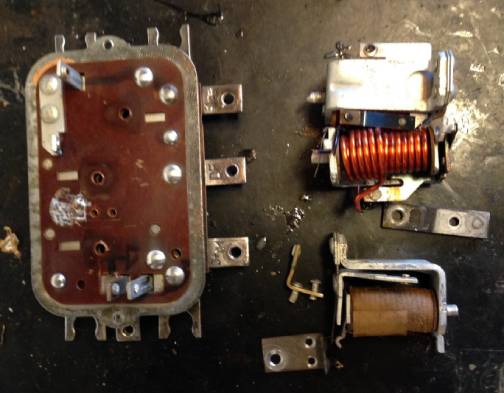
Step 2
Do not just bash away at the internals. You don't want to damage the phenolic mounting surface. Use a Dremel or other tool to grind away the rivets for the relays and any extra contacts or mounting hardware you don't care to use. Use a good quality soldering iron to help remove the wire-wound power resistors and disconnect the relays from each other. I used a Weller 42 Watt with the large wedge 700° tip.
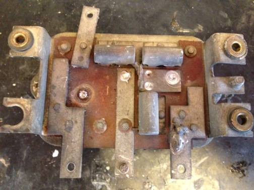
Step 3
Be prepared to use a digital ohm meter to help figure out which internal contacts, rivets or assorted mounting locations are connected to the labeled external screw terminals. Each regulator implementation may be a little different. There is not one diagram that will suffice to explain all possible scenarios. You will need to be diligent and make diagrams or perhaps even add some jumpers above or below the mounting frame to get the desired configuration.
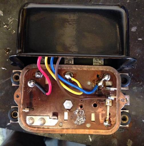
Step 4
Now is a good time to clean all of the metal terminals and any locations you wish to solder. A fine wire wheel works well. I also removed the mangled cheese head screws and replaced them with fresh hardware.
The truly dedicated may decide to strip the mounting frame entirely and send it out for plating.
Step 5
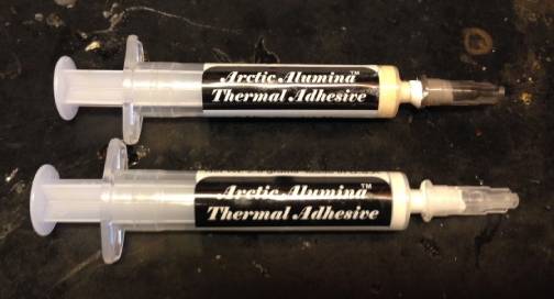
The DVR4 needs to dissipate some energy during normal operations. It comes with a silicone heatsink pad and some mounting holes on the short edges. You’ll need to be creative with mounting. It should make good thermal contact with the housing lid. Silicone thermal grease is widely available. Search the web for “heatsink compound” and you’ll find lots to choose from.
I decided to try something different. I removed the included silicone pad, then used a liberal application of thermal epoxy to affix my DVR4 to the inner top surface of the regulator lid. So far so good.
Step 6
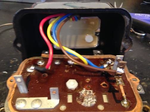
Follow the instructions from ElectroDynamic Solutions and connect the four color-coded wires to the applicable nodes, terminals, or contacts left on the phenolic base of the regulator. Use a good high-quality soldering iron. Go ahead and splurge and use lead-tin solder. Do not use acid-flux!!!
Modern lead-free (RHOS) solder requires higher temperatures. As we are not going to be manufacturing goods for export – don’t bother using it.
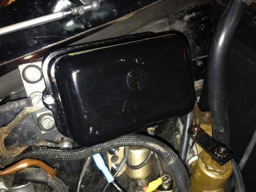
Pay special attention to the brown ground wire. This must be firmly connected in operation. In the image above you can see that I added some additional wire to make multiple ground connections when everything is mounted.
In areas where some mounting stability of the original terminals was lost due to relay or other component removal, I added some nylon screws and nuts for extra strength.
Step 7
I added fresh grommets to the mounting feet and a new decal to the lid. Many of the yellow Bosch decals are available online. I could not find my particular version and ended up making my own in Microsoft Publisher and printing it on water-slide decal paper. Just email me and I’ll gladly share the raw artwork, but a high-resolution set can be found in this PDF file.
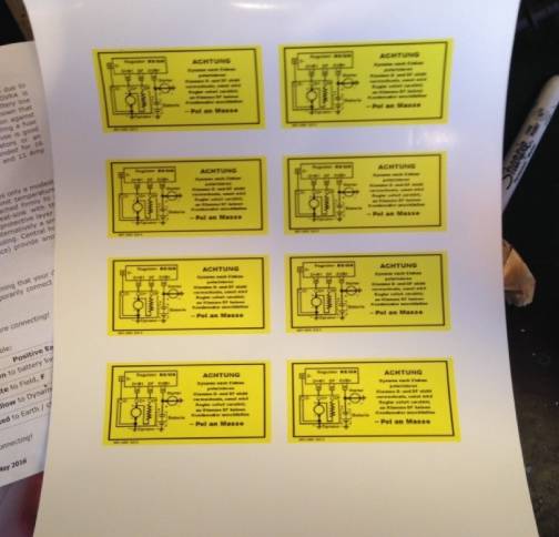
When I made the sheet, I squeezed as many as possible onto the label stock in case of goofs or application accidents. Basically just a bunch of extras to not waste the water slide decal paper.
Step 8
Mount the rebuilt regulator in the same manner as the original. Connect all of the generator harness wires as they were originally. Verify that all the mounting points are clean so that you get a good connection to chassis ground. Consult the instructions provided by ElectroDynamic Solutions.
CAUTION: Your remaining charging system must be in good order. That means no faulty wiring, damaged generators, real fuses in place, etc.
I have been running this system for about two years. My headlights are bright. The generator warning light functions as it should. The ammeter on the dash is at the neutral position even with lights enabled.
Supporting Documents
- Reproduction Bosch labels – copied from an original regulator out of a 1954 Mercedes-Benz Type W186 300 sedan.
- DVR4 technical specifications
Created: February 9, 2019 / Jeff Miller
Revision B / July
13, 2021 / Updated links. Replaced Dynamo Regulators with
ElectroDynamic Solutions
Last Update:
July 13, 2021
© www.mbzponton.org
Return to the Ponton Workshop page