by Terry Morgan / t_zmorgan@msn.com
This is the story of the restoration of my 1959 220S sedan up through January 1998.
Engine Rebuilding
The engine was retrieved from the shop and I cleaned the block with warm water, engine degreaser, and lots of soap. I coated the cylinders with oil afterwards.
Pistons and rods: I weighed each con rod to see if they were within weight difference limits. The total rod weights were within 5 grams. I intended to rig a way to accurately weigh each end so I would know which end to remove metal from, but decided this was probably going too far. I did some polishing on each rod to remove some nicks (which are potential stress risers that can start a crack), and generally polished the heaviest rod to try and lighten it a little.
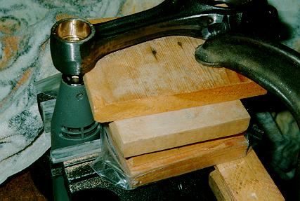
After about 1956, Mercedes used the same rods in both the 220SE and the 220S. The piston pins were 22 mm in the 220S and 24 mm in the 220SE, accomplished by simply using a thicker bushing in the rod ends. The 220SE pistons are significantly cheaper than 220S pistons, so I ordered 220SE pistons and had the machine shop ream out the rod bushings to 24 mm; that removed the original internal oil groove on the inside, as expected. Shop said they could not re-cut a new one. So I cut the new grooves using a Dremel tool mounted in vise and moved rod carefully by hand. See pictures for the setup I used. Not pretty, but should work.
|
Recutting oil groove in rod bushing. Dremel tool was gently held in vise and wood blocks were clamped down to vise. Rod end was moved, with careful pressure, in a circle around spinning tool. Then Dremel tool was raised a little and cut made at a different level. Three cuts were made. |
I weighed all the new pistons to make sure they were within specs. All but one weighed within one gram, much better than I expected -- pretty good quality control from Mahle. With Dremel tool, I ground out enough inside the skirt to bring the heaviest one to average weight of others. I checked end gap of top ring during installation, and it was within spec, so I didn't check the others; the manual says that if rings come installed on new pistons, no need to check gaps (!).
| Rod bolts fit a little tight (by design). I tapped out old ones with hammer; I wouldn't do this to good ones, but nevertheless, they did not require hitting so hard as to damage the threads (I initially tried to rig a way to hold the rod in the vise and press out bolt by closing vise, but was too much trouble). The new ones I tapped in far enough to allow putting a part with a hole in it (a stack of washers would work just as well) and a nut on the end, then turned the nut to draw the bolt into place in the rod. I then spent almost an hour measuring (with a 3 inch micrometer) the length of each bolt and recording it (recorded by rod number and side). After pistons were installed, I measured the lengths after I torqued them to near the spec of 3 m-kg (they are supposed to be torqued to a stretch of 0.1 mm). This was quite a pain and required frequent checking and rechecking. Torquing the nuts to a spec is much faster and easier, but Mercedes must have had a good reason for wanting to measure bolt stretch rather than simply torquing them. One caution on measuring: the thread end is not ground off exactly square, so moving the micrometer end a little to one side reduces the measurement obtained (by a few thousandths) from that obtained if the mic end is exactly centered on the bolt. I tried to "standardize" on having the micrometer centered on the end. Then I measured them all again to check my numbers (good thing I checked!). | 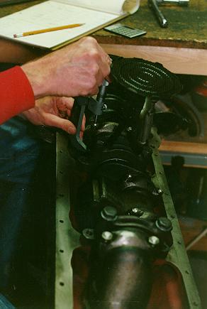 |
| Measuring connecting rod bolt stretch using 3 inch micrometer and lots of patience |
|
|
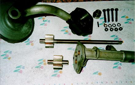
Oil pump: Tolerances were near the wear limits. The alloy (top) part of the housing was well scored, and a friend with a lathe resurfaced this to remove the scoring, which should improve pressure. |
| Oil pump disassembled. Surface on alloy part was resurfaced to remove scoring. |
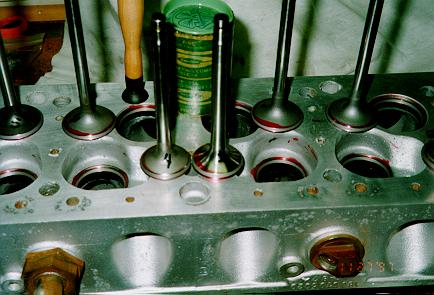
| Valve lapping: A friend showed me how to lap the valves. First apply the indicator dye to both the valve and the seat area. Using the lapping compound and a stick with a suction cup on one end, I started with the coarse grit. You put a little compound around the valve seat area, insert the valve, and spin the suction cup between your hands to spin the valve (a lot like starting a fire with two sticks!). The machine shop did a very consistent job with their valve grinding and seat surfacing, and the coarse grit was mostly unnecessary. The grey area where the dye is rubbed away shows where the contact area is and you can easily see the size and shape of the contact area. (Don't get any lapping compound on the valve stem and then into the guide!) |
|
| Lapping valve seats. Lapping compound is in green can, stick with suction cup is used to spin valve. Grey areas where red dye is gone, on both valve and seat, show valve seat contact area. |
New valve springs are several mm taller than old ones (the shop tested the old ones and said ALL were too weak), so should get significantly more valve seat pressure which should help valve life.
I did some minor porting in the head (using air die grinder and porting/polishing abrasives rolls as sold by Eastwood). There were some significant ridges and lumps in the valve bowl area (below the valve seats), especially in the exhaust ports, and removing these should make a small but significant difference. Elsewhere, I did not polish the surface, but left it relatively rough, as original, so it helps atomize the fuel mixture.
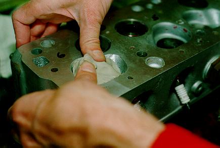
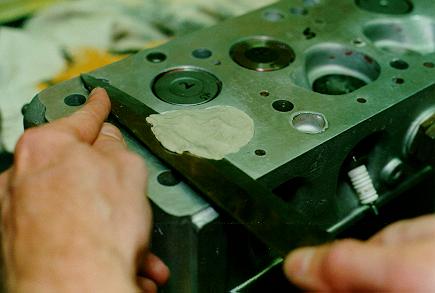
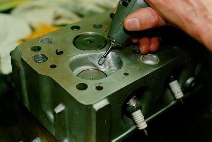
Measuring the combustion chamber volume: I did not have access to a chemistry burette (used for titrating solutions), so I used clay, shaved it off level with cylinder head surface, and then weighed it. I used the end of a cork to plug the spark plug hole and screwed in spark plug to a level that held cork even with inside surface. It was more accurate than I thought it would be; several measurements on the same cylinder varied by only 0.2 to 0.3 grams (out of about 60). One cylinder was significantly smaller than the others, so I swapped a valve that had a different relief pattern, did some grinding on the inside of the chamber, and got it within almost one "gram" of the others.
 |
 |
 |
Upper Left--Using clay to measure combustion chamer volume; pressing
clay into chamber.
Upper--After pressing clay into combustion chamber, it was cut off level with cylinder surface and then weighed. Left--Using dremel tool to remove metal to increase combustion cylinder volume. |
So why go to so much trouble to get the chambers the same? Because if one cylinder has significantly more compression, it may tend to ping before the others, requiring you to set the timing less than optimum for the other cylinders. A true fanatic about blueprinting an engine would work at it much longer than I did. Your average mechanic generally won't even check the chamber volumes, rod weights, head porting, etc., let alone fix it (after all, he gets paid by the hour and most customers won't pay for this). Expenses so far: Pistons of first oversize ($125 each) Rod bearings $85 Main bearings $105 Valve springs (all 24) $5 and $3 each (outer and inner, respectively) $96 Intake valve $18 Exhaust valve $45 Head gasket set $105 Bottom gasket set $80 Bore and hone cylinders $66 Valve job $52.50 Install new guide $3.75 Recondition rods $36 Ream piston pin bushing $96 Grind crank $80 Check valve springs $12 Surface head $20 Pressure test head $20 Machine shop total: $416.87 sub-frame rubber mounts (six pieces) $83 Transmission seal kit $35 Two trans synchromesh $45 each Other small rubber parts, such as suspension pivot seals, tie rod end boots, damper shear blocks.
|
|
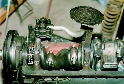
Assembled "bottom end" of engine |
Still trying to find out if first gear synchro is different or has been superseded so they are all the same. A few of the gaskets in the gasket set I received were not correct. Parts people don't know why and only have one listing for all trannys. I reused the old top gasket and "peened" the rear cover gasket to mark it and then cut it to fit. Still need to double-check the bearing clearances and shims in the front and rear cases. Friend with lathe made a part in just a few minutes for driving seal into front cover (don't try it without something that fits properly; you'll do more damage than good. If you want to borrow my tool or make one, contact me). Rear seal is easy and needs no special tools.
Steering
The steering damper is completely out of oil and ineffective, but the new ones are over $210, so I'm attempting to disassemble it. It's partially apart but haven't figured out how to get the piece off the end of the cylinder. Anyone ever cut one open?
 |
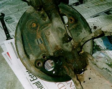 |
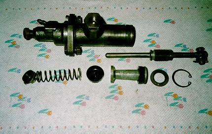
| Brake master cylinder, disassembled. Cylinder was in amazingly good condition and did not require honing | Front suspension spindle and brake backing plate in dirty, as-disassembled, condition. |
Nothing else done so far on front end.
More to come as progress is made.