Joe Alexander / ja17@worldnet.att.net / Blacklick, Ohio
The earliest fuel level sending units had varnished cork floats, which will eventually become fuel soaked and sink! In late 1956, the cork floats were phased out and the units were improved with plastic floats. These plastic floats had spider like additions on the ends to lessen float bounce. The float in Photo 1 does not have these additions. See Photo 2 for the "anti-bounce fingers." To repair a sending unit with a gas-soaked cork float, I have cut the wire arm holding the bad float and brazed on a wire arm with a good plastic float.
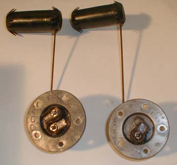
Photo 1.
Fuel level sending unit assembly
Courtesy: Andrew H. Litkowiak
Photo 1: From left to right: plastic float, metal arm, pivot point, sending unit with internal resistance coil, cover plate and finally, the electrical contacts (terminals "W" and "G"). When this assembly is installed in the gas tank, the cover plate and terminals are accessible from inside the trunk.
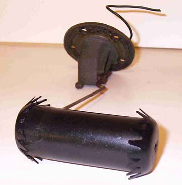
Photo 2. An example of a float with the "anti-bounce fingers"
Courtesy: Bruce Bristow
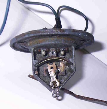
Photo 3. Internal view of the sending unit with float arm attached
Courtesy: Bruce Bristow
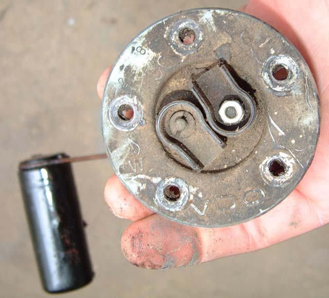
Photo 4. Detail of cover plate with terminals "W" (at left) and "G" (at
right)
Courtesy: Andrew H. Litkowiak
In this photo, you can see the "W" on the left side and the "G" on the right side. Also note the manufacturer's logo, "VDO" at the bottom of the plate.
If your Ponton has a fuel reserve (low fuel warning) light on the dash, then your sender has three wires going to it. The brown wire is ground (the lug is screwed down under one of the 8 mm nuts on the cover plate). The blue wire from terminal "G" (at the sending unit) goes to the dash fuel gauge. The black wire with the blue stripe goes from terminal "W" (at the sending unit) to the reserve light. The low fuel warning light has a 4 to 7 minute delay built into the sender so it does not flicker on and off. The delay mechanism is built inside the instrument unit. A bimetallic strip is heated when the gauge contact for the reserve is closed. When it is closed long enough, it causes mechanical displacement and the bimetallic strip lights the lamp. Grounding the reserve light will result in a delay before the lamp comes on.
Photo 5. Comparison of two different sending units
Courtesy: Joe AlexanderHere is a photo of the two different senders. The one with two wire terminals is for sedans with a low fuel warning light.
Inside the sending unit, a contact rubs on a coil and changes position in relation to the fuel level. The change in resistance is registered as fuel level on the dash gauge. Moisture or wear cause problems with these delicate mechanisms. If your fuel gage "flicks" hard against the full peg every time it reaches a certain level the delicate wire coil in the sender is probably worn and damaged. If your gauge does not move at all your sender mechanism may be stuck from moisture and corrosion.
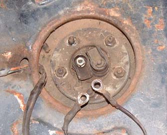
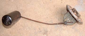
Photo 6. Fuel level sending unit as seen from inside the trunk
Courtesy: Andrew H. LitkowiakThese sending units are easily accessed through the trunk. Lift the mat and pop off the black rubber cap in the center of the trunk. The five 8 mm nuts can be removed and the unit can be lifted out of the gas tank. Sometimes these 8 mm fasteners are rusted frozen so you may want to soak them with your favorite penetrant first.
A cork gasket is used between the cover plate and the trunk floor to seal the unit. Have a new cork gasket on hand for re-installation. They are readily available. Note that if it smells like gasoline in the cabin, it may be due to a deteriorating gasket.
If you leave the wires hooked up to the sender you can turn the ignition on and manually move the float arm while viewing your fuel gauge for operation through the rear window. Take this opportunity to take a flashlight and look into the fuel tank to see if you have a rust or contamination problem.
| CAUTION: Avoid using a trouble-light, smoking, open flames, or any other source of ignition while working with exposed gasoline. Any sparks from static or electrical shorts can be disastrous. Have a fire extinguisher nearby. Proceed at your own risk. |
Fuel Sender GasketIf it smells like gasoline in the cabin, check the fuel sender gasket! "All during my cross-country trip last fall, whenever the tank was filled up, I smelled gasoline inside the car, and especially inside the trunk. The fuel gauge worked fine — even showing the red warning light when fuel level was low. The odor gradually disappeared as the fuel level got lower. I never found a leak or plugged vent anywhere. The fuel sender nuts were tightened down on the studs, yet the smell continued. Today, I decided to check the sender gasket itself. I removed the rubber cover, and found the top of the sender wet with gasoline. I had just filled the tank, and fuel had been sloshing up and out onto the top of the tank itself."
Photo 7. Fuel Sender Gasket
"This photo shows my gasket: withered, cracked and worn out (hmm, sounds a bit like me). The old cork gasket was compressed flatter than a piece of card stock." |
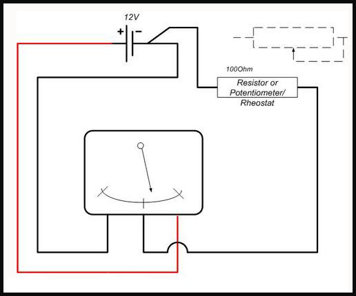
Illustration 1. Test Circuit for Mercedes-Benz Ponton fuel gauge (on the workbench)
Courtesy: Igor Huygen / April 3, 2007You can also test the sending unit on the bench with an ohmmeter. Full tank = 180-190 ohms, half full = 109 + or - 3 ohms, one quarter full should be 60 + or - 3 ohms.
With a 100 ohm resistor in series (see Test Circuit schematic) the reading on the fuel gauge should be about half-scale. To vary the fuel gauge reading, try a variable resistor (potentiometer, rheostat) of about 200 ohms or higher. Do not connect the ground cable directly to the fuel sending unit connection on the gauge because it will damage the gauge. There needs to be something to limit the current, and that is what the resistor is for.
References
Jobs 47-2 and 47-3 in the Service Manual Model 190 (SM-1207-000) provide more detail with photos and illustrations