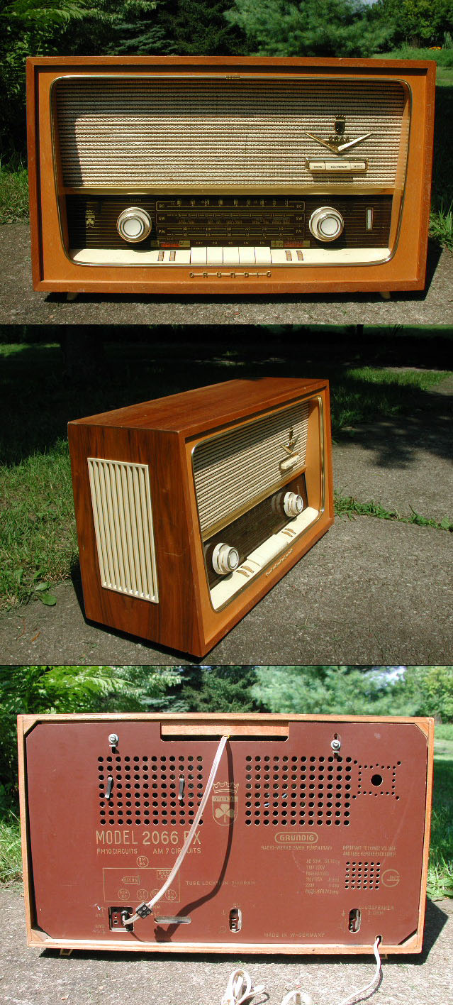
Photo 1. Grundig "2066 PX"
Grundig Werke Fürth (Bayern) "Model 2066 PX" (1089-101)
(West Germany)
Years Manufactured: 1958-1959
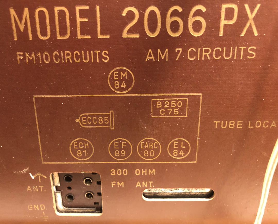
Valve (tube) Line-Up: ECC85 (6AQ8), ECH81 (6AJ8), EF89 (6DA6),
EABC80 (6AK8),
EL84 (6BQ5), EM84 (6FG6)
Tuning Range
Broadcast (AM): 510 - 1620 kHz
Short Wave: 5.9 - 16 MHz
Frequency Modulated (FM): 88 - 108 MHz
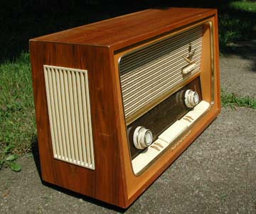
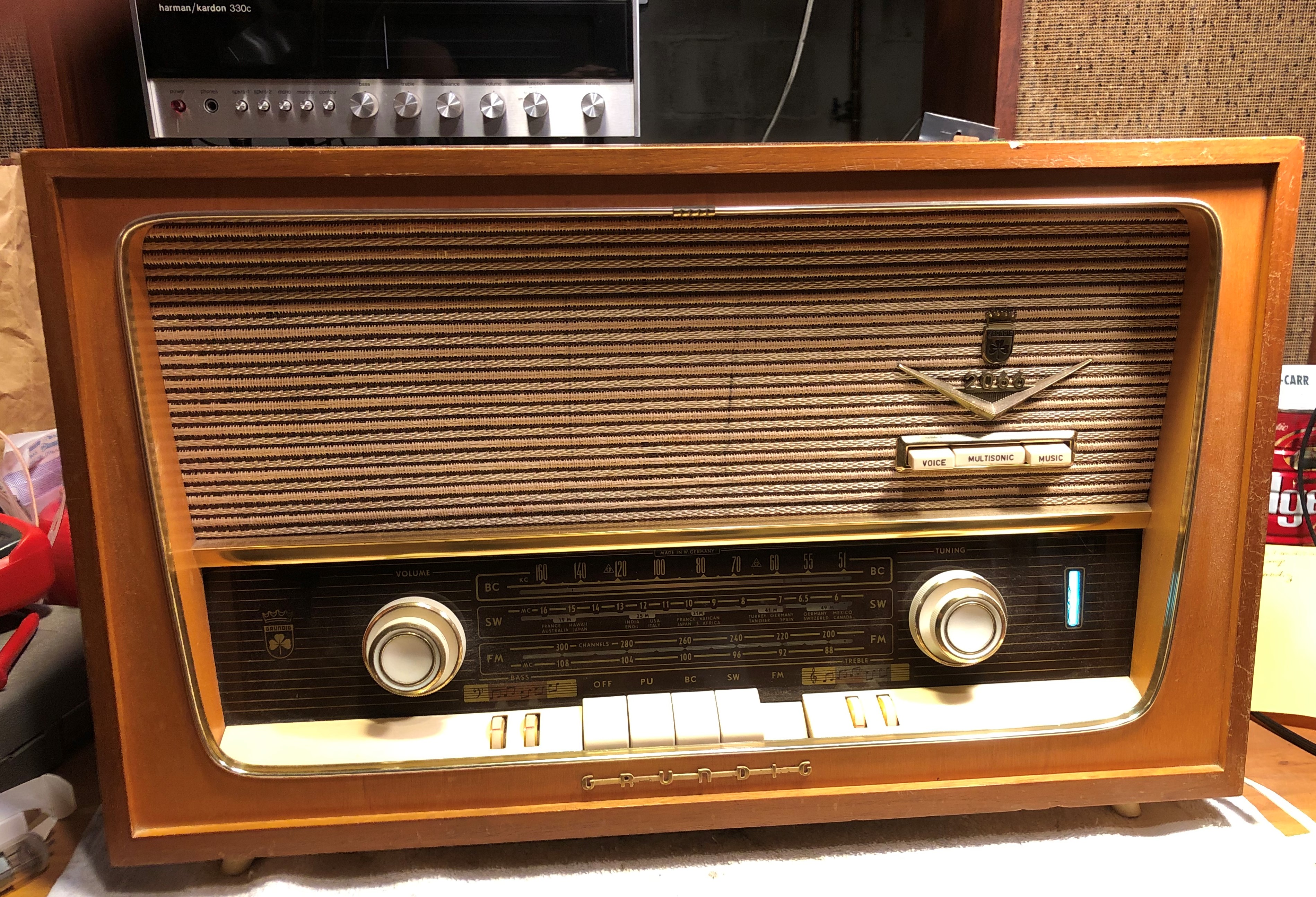
Photo 2. Grundig 2066 PX / August 18, 2004
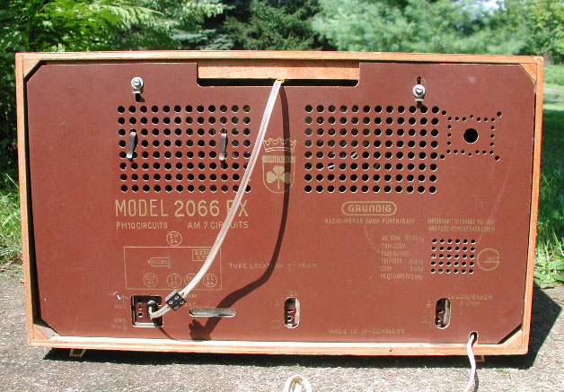
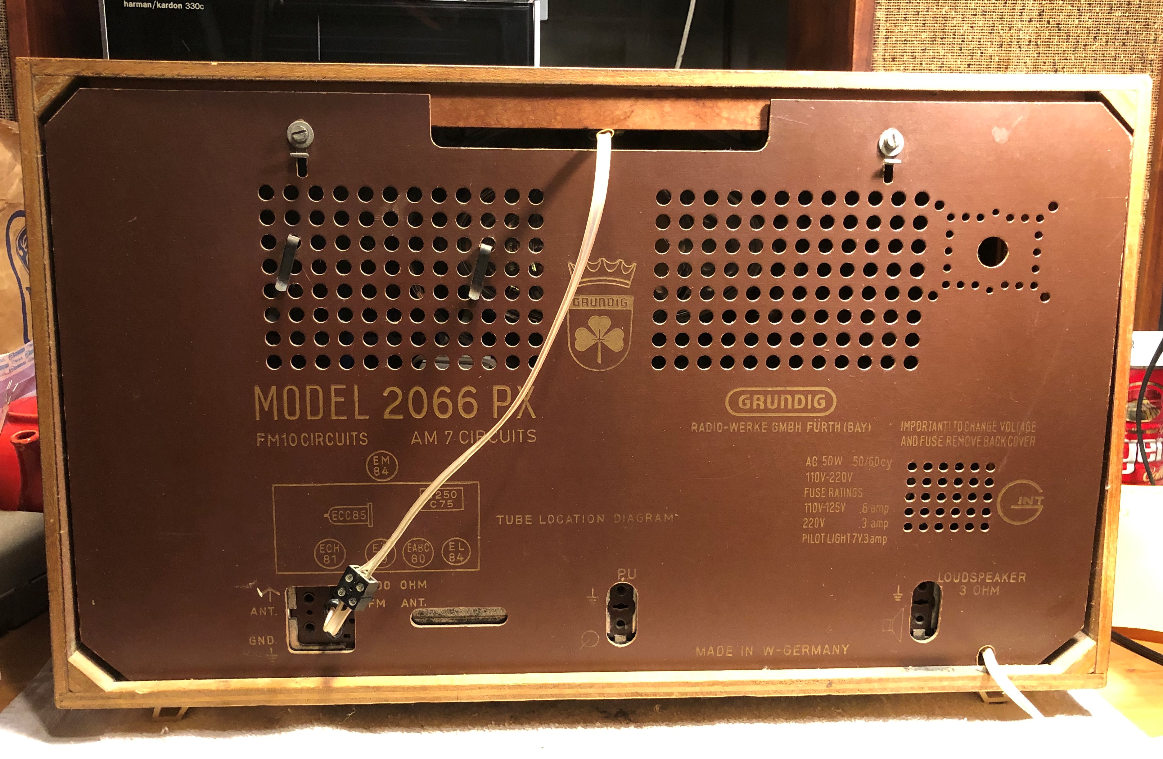
Photo 3. Rear view of Grundig 2066 PX / August 18, 2004
| Table 1 Grundig 2066 PX Valve ( tube ) line-up ( 6 total ) |
||
| Original Tube | Cross Reference | Tube Type |
| ECC85 | 6AQ8 | Double Triode VHF-tube (FM tuner section) www.r-type.org/exb/exb03323.htm |
| ECH81 | 6AJ8 | Triode-Heptode Frequency converter controlling "mu"
(Greek letter µ = symbol for amplification factor) (AM converter, and FM first IF
stage) www.r-type.org/exb/exb03328.htm |
| EF89 | 6DA6 | Pentode RF/IF-tube controlling "mu" (Greek
letter µ = symbol for amplification factor) IF stage (Intermediate Frequency) for both FM and AM reception.
(affects audio level) www.r-type.org/exhib/aaa0270.htm |
| EABC80 | 6AK8 | Triple Diode-Triode Detector tube. Used in AM and FM
detection, and the first audio amplification stage. www.r-type.org/exb/exb03299.htm |
| EL84 | 6BQ5 | Pentode Power tube (audio amplification) www.r-type.org/exb/exb03367.htm |
| EM84 | 6FG6 | Tuning indicator tube ("magic eye") www.r-type.org/exhib/aaa0079.htm |
Overview
This 1958-1959 Grundig "2066 PX" AM/FM/SW vacuum tube (valve) radio was in nice cosmetic condition when I found it on August 18, 2004. However, it was a weak performer, incapable of producing the big, robust audio for which these radios earned a strong reputation.Day One
I purchased this "2066 PX" on August 18, 2004 at the annual Antique Wireless Association (AWA) conference and outdoor swap meet in Rochester, NY. It was a balmy summer day, and it was the first time I attended any such antique radio event. The seller, Phil Clayton of Syracuse, was asking $125, but after lugging it inside to plug into the conference room mains, and getting more familiar with the features and details, he agreed on $75.
Closer Inspection
Once home, I discovered a lot of dust inside, but it was functional and seemed to be 100% complete and original. I cleaned the radio inside and out, and it was looking good. The volume control was difficult to turn, but applying some light oil to the shaft loosened it up a bit. However, after 46 years, the veteran's performance seemed to be a few notches below original specification. After a few weeks, I broke through my threshold of disappointment and decided to put my skills to use and replace some of the components responsible for pulling the performance down, and attempt to make it sound like new again. Thus, my first attempt at a radio restoration had begun. The rest of this page details my experience and findings in that endeavor.Pilot Lamp
Tuning dial pilot lamp (one required) is Type 40, 6.3v, 150mA (0.15A) miniature screw base, cylindrical bulb, clear glass. Tuning dial pilot lamps are available from Radio Daze for $0.35 each. They can also be found at local radio swap meets, sold as Type 40 pilot lamps, usually ten per package.
PX
Some Grundig radios were sold in the US military exchanges (the PX "post exchange" for US Army personnel). The items sold through the exchange could be identified with the model number followed by the suffix "PX."Schematics
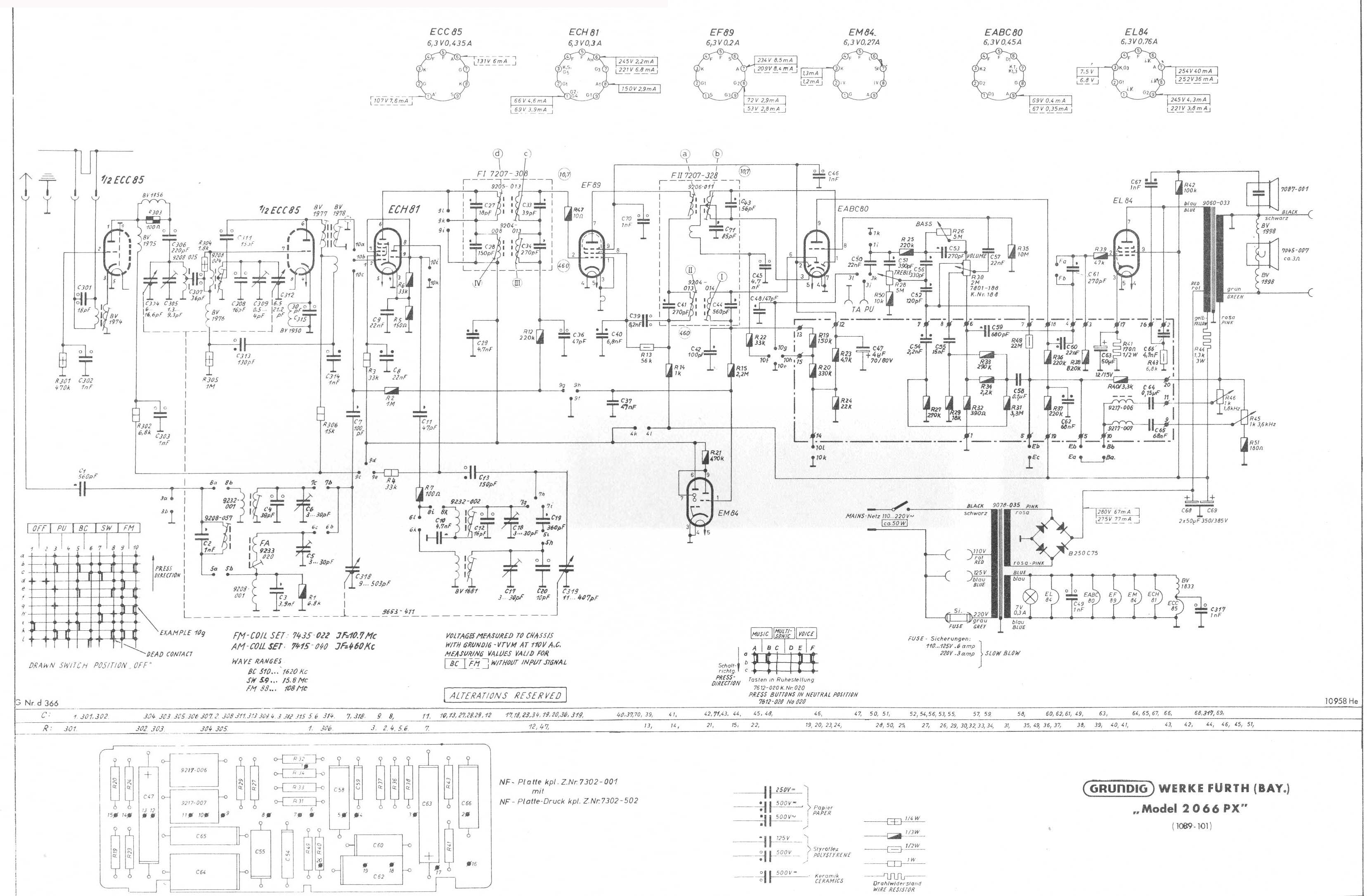
- Grundig 2066 PX schematic (.pdf / German / courtesy: Daniele in Italy)
- Grundig 2066 PX schematic (.jpg / Circuit board layout detail)
- Grundig 2066 PX schematic (.jpg / English / courtesy: Hans M. Knoll / 06-sep-2005)
- Sam's PhotoFact packages are not available for the Grundig 2066 PX (courtesy: Dave Cantelon of Just Radios 14-aug-2005)
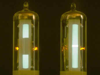
Photo 4. EM87 Magic Eye Tube
EM87 "Magic Eye" tuning tube (similar to EM84).
Left: quiescent state. Right: appearance when tuned to a strong signal.
The Grundig 2066 PX radio uses the similar, EM84 tube.
The EM87 tube is shown here for reference only.
The EM84 (6FG6) Magic Eye tuning tube is available from Radio Daze for $6.50.
The EM84 "Magic Eye" Tuning Strength Indicator Tube Overview
The EM84 Magic Eye (in German, "Magische Augen") indicator tube is a standard thin glass tube envelope with a phosphor strip on the inside of the side glass. The electrode structure is based on a double triode with common cathode. The anode of the second triode is called the target and within the electron stream is a deflector electrode designed to alter the path of the electron beam. It would normally be connected to the anode. In the EM84 the quiescent condition was two green bars, one at each end of the window. As the signal strength increased (and the grid voltage is decreased), the bars would elongate and eventually overlap to form a bright green region. The optimum point for tuning was a minimum gap, and for monitoring peak levels, the operator was told to have the bars just barely touching (but not overlapping) on peaks. See References.August 2004:
The phosphor bars of the EM84 tuning indicator tube in this Grundig 2066 PX radio would barely move when tuned to a strong radio signal. The two bars are supposed to lengthen as the grid voltage decreases (as the radio signal strength increases) until they meet. I hope to fix the problem by replacing the old paper capacitors. Also need to measure and verify that the EM84 grid voltage (pin 1) is changing. Voltage should be decreasing as the signal strength increases. Check values of R15 (should be 2.2M Ω) and R21 (470k Ω) See notes below. I believe I replaced the EM84 tube when I first got the radio, but I have not located the receipt for that tube.20-aug-2004:
Comments from the rec.antiques.radio+phono vintage radio discussion group regarding the Grundig 2066: AGC = Automatic Gain Control, and is sometimes known as AVC (Automatic Volume Control). The magic eye tuning indicator does not have anything to do with the sound quality. You can easily check the AGC voltage by measuring the voltage on the EM84 grid (pin 1). Replace each and every wax paper capacitor. They all leak today. One is probably dragging down the AVC line, thus not letting the eye tube close more. Other capacitors can cause mis-biasing of the audio amplifiers and elsewhere. Change one at a time so you do not lose track of where its replacement goes. I would not replace the tubes at this point. Only ones proven to be bad. Tubes are surprisingly seldom at fault in radios this old. Tubes sitting idle do not degrade, but the wax capacitors do degrade over time, idle or not.
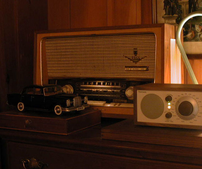
Photo 5. Grundig 2066 PX Before Restoration
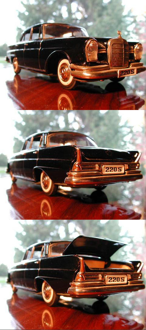
19-jan-2005: This photo shows the radio before the decision was made to restore. The set would play, but had some crackling noises in the audio, and the volume control was semi-functional, the magic eye tube was not fully closing on strong signals, and the maximum volume was low. Not uncommon symptoms for a 50 year old radio. Also shown: Tivoli "Model One" AM/FM monaural receiver.
The toy car in the photo is a 1:18 scale (approximate) tinplate Mercedes-Benz Type W111 220Sb "Heckflosse" (a.k.a. "Fintail") sedan. It has a black body with a red/amber striped lithographed interior. It features a trunk lid that opens to reveal two levers. One lever is used to raise the left or right-side clockwork-motor-driven "jack" under the car. This simulates changing the tire. The other lever toggles which side of the car is raised. The wheels come off by unscrewing the hubcaps. The toy was distributed in 1962 by Shioji Shoten & Co. Ltd. of Osaka, Japan (SSS). I paid $150 for it in June 1997 at an antique toy show. It was missing the spare tire and wrench, but the hood star was intact. Collectors will pay a premium for a complete unit, especially if it includes the original packaging. There is a variation of this model that requires two C-cells and features working headlights. The lights are activated by raising the antenna.
04-nov-2006:
This link: EM84 says the maximum voltage applied to control grid with respect to cathode (normally at ground) is -22 volts. I measured -1v volt at the grid and is cause for investigation. Negative 22 volts is required to close the EM84 bars. Check value of R21 (470k) because when the voltage to pin 9 is low, the bars will not close. Verified the value of R21 at 470k. Measured 230v on other side of R21 coming from R15. Need to locate R15 and verify its value. At this point, I hope to test all the tubes in the set before I go any further.
Volume Control Saga
18-aug-2004:
At first, the volume control was nearly impossible to turn. The seller sprayed some kind of lubricant on it while we stood at the back of his car in the parking lot of the AWA conference. That only helped a little. When I got the radio home, more problems began to surface. The volume control could be turned in the clockwise direction without reaching any maximum position. Perhaps the knob was slipping or the internal stops of the potentiometer were damaged.03-sep-2004:
The chances of finding a new potentiometer were limited. Here is a response to a question I posted on the rec.antiques.radio+phono usenet group."Finding a volume control potentiometer will be virtually impossible. These controls usually have a couple of loudness taps and were specially made for the radio. You can substitute a standard audio taper pot of the same value, but the radio will not sound the same because the taps will be lost. Your only chance would be to get one from a junker."
According to the schematic, R30 (2M Ω, "7801-188 K.Nr. 188") is the volume potentiometer. It has a wiper and four taps off it. I originally intended to break it down, clean, and re-assemble it.
30-oct-2006:
After a 13 month hiatus from the project (September 2005 to October 2006), I determined that the volume control potentiometer obtained during my visit to Bavarian Radio Works (01-sep-2005) was a different value (1.3M+ K146 428) and pin-out from the one in the radio. The potentiometer (R30) in the radio was stamped "2M+ 328 K188", which matched the schematic annotation. A more experienced radio technician may have been able to deal with this minor contingency and make the substitute potentiometer work in this radio, but for me, it represented an obstacle that I wished to circumnavigate, until all other possibilities were exhausted.It was suggested that I contact Mark Oppat of www.oldradioparts.net in Michigan. I did that, and he told me that if I could not get mine working, he would be willing to attempt a repair.
A few days later (30-oct-2006) a very kind radio enthusiast from near the city of Dortmund, Germany read an online forum post, and sent me the exact potentiometer (K188) that the Grundig 2066 PX radio requires. My appreciation and thanks go out to Dr. Stefan Weigelt for supplying this critical part. Replaced the volume control potentiometer R30 on November 4, 2006.
| Table 2 Original list of parts ordered to restore the Grundig Type 2066 PX (Compiled: 04-sep-2005 through 06-sep-2005. Placed order: 06-sep-2005) |
|||||||||
| Schematic part number |
Original component and composition | Value (original) | Value
(replacement) |
Composition of new part |
Mouser (800-346-6873) part number |
Price |
Quantity |
Ordered |
Total |
C68, C69 |
Capacitors (2) to replace power supply filter (2 in 1 canister) | 47µF,
350V |
electrolytic (aluminum w/ blue
vinyl sleeve) |
140-XRL350V47 Mouser cat 623 / pp 534 |
$0.96 |
2 |
4 |
||
| C21, C50, C57, C60 |
Capacitor (paper) |
22nF, 500V |
0.022µF, 600V |
orange drop polypropylene |
75-715P600V0.022 Mouser cat 623 / pp 595 |
$0.47 |
4 |
8 |
|
| C40 |
Capacitor (paper) |
6.8nF, 500V |
0.0068µF, 600V |
orange drop polypropylene |
75-715P600V0.0068 Mouser cat 623 / pp 595 |
$0.53 |
1 |
4 |
|
| C62, C65 |
Capacitor (paper) |
68nF |
0.068µF, 600V |
orange drop polypropylene |
75-715P600V0.068 Mouser cat 623 / pp 595 |
$0.94 |
2 |
4 |
|
| C37 |
Capacitor (paper) |
47nF, 250V |
0.047µF, 600V |
orange drop polypropylene |
75-715P600V0.047 Mouser cat 623 / pp 595 |
$0.77 |
1 |
4 |
|
| C29 |
Capacitor (paper) |
4.7nF, 500V |
0.0047µF, 600V |
orange drop polypropylene |
75-715P600V0.0047 Mouser cat 623 / pp 595 |
$0.47 |
1 |
4 |
|
| C47 |
Capacitor (paper) |
4.0µFsize="-1">F, 70/80V |
Substitute 4.7µF (63 to 100V).
The greater value (4.7) has no affect on the function of the radio. Tolerance of small electrolytic capacitors is +/- 20%. |
electrolytic (aluminum w/ blue
vinyl sleeve) |
140-XRL160V4.7 Mouser cat 623 / pp 534 |
$0.07 |
1 |
4 |
|
| C54 |
Capacitor (paper) |
2.2nF, 500V |
0.0022µF, 600V |
orange drop polypropylene |
75-715P600V0.0022 Mouser cat 623 / pp 595 |
$0.47 |
1 |
4 |
|
| C55 |
Capacitor (paper) |
15nF, 250V |
0.015µF, 600V |
orange drop polypropylene |
75-715P600V0.015 Mouser cat 623 / pp 595 |
$0.60 |
1 |
4 |
|
| C58 |
Capacitor (paper) near R31 |
0.1µF,
250V verify |
0.1µF, 600V |
orange drop polypropylene |
75-715P600V0.1 Mouser cat 623 / pp 595 |
$1.22 |
1 |
4 |
|
| C67 |
Capacitor (paper) |
1nF, 500V |
0.001µF, 600V |
orange drop polypropylene |
75-715P600V0.001 Mouser cat 623 / pp 595 |
$0.47 |
1 |
4 |
|
| C64 |
Capacitor (paper) |
0.15µF, 250V |
0.15µF, 600V |
orange drop polypropylene |
75-715P600V0.15 Mouser cat 623 / pp 595 |
$1.47 |
1 |
4 |
|
| Resistor (load the silicon rectifier that replaces selenium rectifier) | 100 Ω, 10W |
XICON 5% cement power resistor |
280-CR10-100 Mouser cat 623, pp 462 |
$0.55 |
1 |
4 |
|||
| Resistor for FM tuner (if applicable) | 150 Ω 10% | carbon composition (¼W or ½W ?) (brn-grn-brn-silver) |
30BJ250-150 (¼W) 30BJ500-150 (½W) Mouser cat 623, pp 462 |
$0.63 (¼W) $0.77 (½W) |
1 |
||||
| Silicon bridge rectifier to replace selenium rectifier | 3A, 400V |
583-BR34 Mouser cat 623, pp 319 |
$0.46 |
1 |
3 |
||||
| not needed for restoration | Banana plug (black) |
174 R8 22B Mouser cat 623, pp 810 |
$0.92 |
3 |
3 |
||||
| not needed for restoration | Banana plug (red) |
174 R8 22R Mouser cat 623, pp 810 |
$0.92 |
3 |
3 |
||||
Notes / September 2005
Began making the following notes and/or obtained the following parts to further the restoration of the Grundig 2066 PX while visiting Ross Hochstrasser (W1EKG) of "Bavarian Radio Works" on September 1, 2005. Ross was very generous with his time and it was a pleasure to spend an afternoon with him (about five hours total) in his shop. Most parts are available from the Mouser website unless noted.
- Volume control potentiometer (removed from similar radio chassis).
- Replace all paper capacitors with "orange drop" polypropylene type.
- Replace specific electrolytic capacitors with electrolytic (aluminum w/ blue vinyl sleeve) type.
- Silicon bridge rectifier (has 4 leads: "+", "-", and 2 sine waves for AC input). The "+" (plus) goes to the load resistor (100 Ω, 10W), "-" (minus) goes to ground and the sine wave leads go to the transformer (see schematic). Mouser p/n: "583BR34" (3A, 400V). This rectifier will replace the original selenium rectifier. Note that the selenium rectifier is considered a semiconductor device.
- Load resistor (100 Ω, 10W) for use with new silicon bridge rectifier. Mouser p/n: "280-CR10-100."
- Ground lug (for the "-" lead of the silicon bridge rectifier) and single node terminal strip for soldering the "+" lead of the bridge and load resistor to. Mouser should have the ground lugs, but not sure about the terminal strips. They may have come from Newark or AES.
- Replace the 150 Ω 10% carbon composition resistor (brn-grn-brn-silver) in the FM tuner (if applicable). Verify whether the 2066 PX radio has this resistor or not.
- Need a 5.5 mm open end wrench to remove the FM tuner housing (see Notes section below table).
- Replace power supply filter capacitor (large, aluminum, canister type) which is wired to rectifier, with electrolytic (aluminum w/ blue vinyl sleeve) type capacitors. Need (2) 4.7µF 350Vdc capacitors to replace the large canister filter capacitor. Mouser part number for new caps: "140XRL350V47."
- Use "Deoxit D100" (red liquid with needle applicator) on tube pins $14/bottle. MCM catalog.
- When replacing paper capacitors, select a unit with exactly the same capacitance rating and a WVdc (DC Working Voltage) rating that is equal to or greater than the original WVdc rating. Carr / p. 129.
- Ordered 25 ml bottle of "Deoxit" (red liquid, use on tube pins) (06-sep-2005).
MCM
650 Congress Park Drive
Centerville, Ohio 45459
800-543-4330
www.mcmelectronics.com
Description: CONTACT CLEANER 25ML DEOXIT RED NONFLAMMABLE
MCM Part No.: 200-070
Manufacturer Part No.: D100L-25C
Precision dispenser 100% solution, 25ml
Caig Laboratories DeoxIT Red Precision Dispenser,
100 % solution, 25 ml
$15.95- Ordered a 5.5 mm open end wrench (from www.sjdiscounttools.com) to remove the FM tuner housing (06-sep-2005). Open end wrench made by Facom. $7.41 plus $11.45 shipping = $18.86 total. Discovered on 12-nov-2006 that this wrench is too short to get to the screw on the bottom of the tuner housing. The length of the wrench handle needs to be at least 6 inches. 7/32 inches is 5.556 mm. Will it work?
| Table 3 Additional parts needed to restore the Grundig Type 2066 PX (Compiled: 21-oct-2006 through 22-oct-2006. Placed order: 22-oct-2006) Ordered online at mouser.com Parts came to $2.32 / Freight charge was $3.31. |
||||||||||
| Schematic part number |
Original component and composition | Value (original) |
Value
(replacement) |
Composition of
new part |
Mouser (1-800-346-6873) part number |
Price |
Quantity |
Ordered |
Total | Date |
| R44 | power resistor
|
1.3k 2% 4W | 1.3k 5% 5W | 280-CR5-1.3K-RC 1.3k 5W 5% Cement Power Resistor | $0.39 | 1 | 2 | $0.78 | 22-oct-2006 | |
| R30 | volume control
potentiometer
|
2M+ 328 K188 | 2M+ 328 K188 courtesy: Dr. Stefan Weigelt |
as original | N/A |
03-nov-2006 |
||||
| Could be C2, C48, C57, C70 which are all "1nF" (same as 1000pF) | Capacitor
Note: 1000pF = 1nF = 0.001 µF |
1000pF, 1000V (per markings on cap itself). | 1000pF, (0.001µF) 1600Vdc | orange drop polypropylene | 75-715P1600V0.001 | $1.30 | 1 | 2 | $2.60 | 22-oct-2006 |
| Mains fuse | Main power fuse | 0.6 A Slow Blow | 0.6 A Slow Blow | Cooper/Bussmann 1¼ x ¼ inch, 250V 0.6A, Time Delay Glass | 504-MDL-6/10 | $1.040 | 1 | 5 | $5.20 | 31-oct-2006 |
Notes / October 2006
Began working again – after taking a year off.
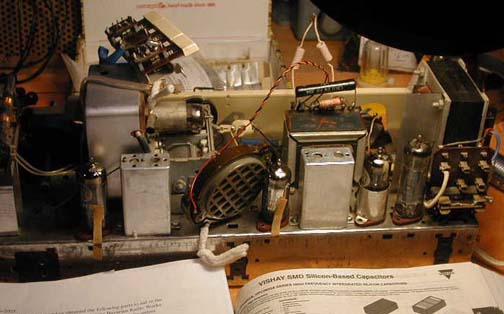
Photo 5. Grundig 2066 PX Chassis
Grundig 2066 PX / October 21, 2006 / rear view
Note the pipe cleaners holding the electrostatic tweeter and tone "contour" switch assembly in place while the wood cabinet is removed.
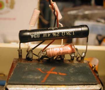
Original paper capacitor (C?* in the schematic): 1000pF 100Vac 1000Vdc. The schematic refers to these 1000pF capacitors as 1nF. The parts vendor (Mouser) refers to them as 0.001µF. Original power resistor (R44 in the schematic): 1.3k 2% 4W. It is okay to use higher power rating on the resistor. I ordered a 1.3k Ω 5% 5W replacement from Mouser. * I have not identified this particular capacitor in the schematic. It is clearly attached to the "9060-033" transformer (see photo), but the schematic shows no capacitor there. The "closest" 1nF cap is C67, but that is not shown attached to the transformer. Please contact me if you know which capacitor is shown in the photo above!
The voltage ratings printed on the body of the capacitor "100 ~" (Vac) and "1000 -" (Vdc) are both significant when seeking replacement. The DC voltage rating is called the Working Voltage. The capacitance rating is 1000 pF. The schematic lists 1000pF capacitors as "1nF." Does the double stripe at one end indicate the positive end as in a polarized electrolytic capacitor? No, the second stripe signifies the outer foil. The outside foil would go to the lower impedance side of the circuit, which might not be the 'ground-ward' side. For instance, in a plate-to-grid coupling application, the lower impedance side would be the plate, so the capacitor's outside foil would preferentially go there. Also, an electrolytic capacitor would never be produced for such a small value capacitor.
Selenium (semiconductor) Rectifier
German radios typically used selenium (semiconductor) rectifiers in the power supply, while Philips (Netherlands) continued to use tubes for this purpose until about 1965. See References.
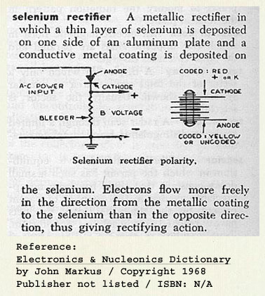
Illustration 1. Selenium Rectifier
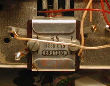
Photo 7. Original "B250 C75" Selenium Rectifier
Weekend of October 28-29, 2006: Resumed work, and was able to remove and disassemble the selenium (semiconductor) rectifier ("B250 C75" on the schematic). Here it is in its original condition mounted on the left end of the radio chassis. Note the "+", "-", and sine wave labels at the terminal posts. I believe the other notations are the manufacturer's logo, Siemens AG perhaps.
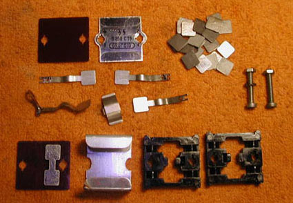
Photo 8. Original, Disassembled Selenium Rectifier "B250 C75"
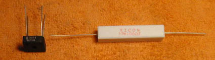
Photo 9. Replacement Parts for Original Rectifier
These are the replacement parts for the original rectifier. The new silicon rectifier (bridge) Mouser p/n: "583BR34" (3A, 400V) and the load resistor (100 Ω, 10W).
The 100 Ω, 10W load resistor is placed in series between the "+" terminal of the silicon bridge and one terminal of the filter capacitors. This is done to compensate for the relative "efficiency" of the silicon rectifier as compared to the selenium (semiconductor) rectifier. The load resistor will keep the current to the filter capacitors (C68 and C69) close to the original value of about 67 mA. The original selenium (semiconductor) rectifier has a lot of discrete parts as compared to the silicon bridge! The squares in the top right of the photo are the selenium (semiconductor) wafers.
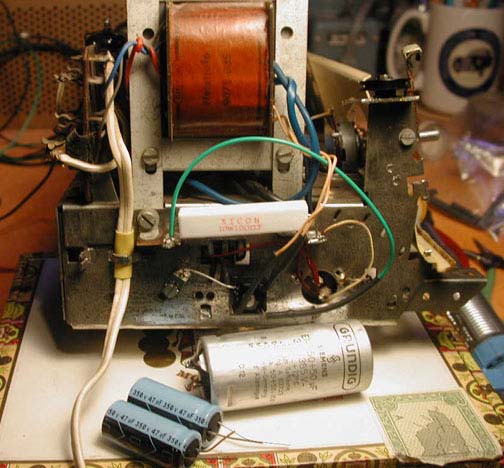
Photo 10. Load Resistor and Silicon Rectifier Installed
The square, black, silicon rectifier is difficult to see but it is there! I re-used the two nuts and bolts from the original "B250 C75" rectifier package as mounting points for the single ground connection (the "-" terminal of the rectifier) and the mount point for the new silicon rectifier. The new rectifier had a hole in the center which was perfect for mounting it in this fashion. I also applied a thin layer of thermal joint compound between the body of the silicon rectifier and the chassis to better dissipate heat. This photo also shows the original filter capacitor canister (C68, C69 / 50 µF, 350V each) and the new electrolytic capacitors (47 µF 350V each) that will replace the canister. The canister came from another radio. The original filter capacitor canister was still installed in the radio when this photo was taken. I replaced the 2 x 50µF capacitor canister with 2 x 47µF caps (photo) and nothing changed.
After replacing all of these parts, the radio still sounded distorted and the audio was popping. I hope the filter capacitors make a difference. I hope to look at the signal on an oscilloscope, before and after replacement of the filter cap canister.
On Sunday October 29, 2006 I was able to use an oscilloscope (B&K Precision Model 1460) to view the output of the new silicon bridge and load resistor. The voltage at the "+" side of the new rectifier measured about 260V. This was within 10% of the specified value on the schematic (280V). As expected, the waveform at the output had some ripple. I placed a single new 50 µF cap in the circuit and it removed most of the ripple. The second capacitor should remove the remaining ripple. Thanks to Tim (WB2PAY) for the the oscilloscope.
Popping Audio
The audio was making a popping noise. This turned out to be a faulty EL84 (6BQ5) audio tube. Fortunately, I had a replacement EL84 tube from another radio and that problem was cleared up. I need to test the original EL84 and see where the fault is. Anybody have a tube tester?Note this problem was resolved by replacing R37, a 220k Ω resistor which was found to be open (infinite ohms). The bypass capacitor C62 was shorted, so all the B+ was going through the resistor and destroyed it.
Tube Testing
The next step is to test the tubes in the radio. The valve (tube) line up in the Grundig 2066PX is as follows (cross references are shown in parenthesis).ECC85 (6AQ8), ECH81 (6AJ8), EF89 (6DA6), EABC80 (6AK8), EL84 (6BQ5), EM84 (6FG6)
|
Table 4 |
||||||
| Original Tube | Cross Reference | Price (Radio Daze) | Date | Tube Type | Tested (AWA Museum) | ordered replacement |
| ECC85 | 6AQ8 | $15.00 (w/ tax) | 05-nov-2006 | Double Triode VHF-tube (FM tuner section) | weak / 28-jul-2007 | Picked up at Radio Daze 01-aug-2007 |
| ECH81 | 6AJ8 | $6.25 | 05-nov-2006 | Triode-Heptode Frequency converter controlling "mu" (Greek letter µ = symbol for amplification factor) (AM converter, and FM first IF stage) | good / 28-jul-2007 | |
| EF89 | 6DA6 | $13.20 plus $9.46 shipping = $22.66 (www.tubesandmore.com) | 30-jul-2007 | Pentode RF/IF-tube controlling "mu" (Greek letter µ = symbol for amplification factor) IF stage (Intermediate Frequency) for both FM and AM reception. (affects audio level) | weak / 28-jul-2007 | Ordered from tubesandmore.com on 30-jul-2007 |
| EABC80 | 6AK8 | $6.00 | 05-nov-2006 | Triple Diode-Triode Detector tube. Used in AM and FM detection, and the first audio amplification stage. | good / 28-jul-2007 | |
| EL84 | 6BQ5 | $21.50 | 05-nov-2006 | Pentode Power tube (audio amplification) | good / 28-jul-2007 | Ordered replacement from Antique Electronic Supply 25-aug-2020 |
| went bad /25-aug-2020 | ||||||
| EM84 | 6FG6 | $7.00 | 05-nov-2006 | Tuning indicator tube ("magic eye") | good / 28-jul-2007 | |
| Total | $65.65 | |||||
Update / 12-nov-2006:
Borrowed a Hickok model 6000A tube tester from Bill (WA2LVP). The tester had the correct settings for the EL84 (6BQ5) tube, but not the other five tubes. I used a European to American tube cross reference booklet. The EL84 (6BQ5) was the only tube it had data for on the scroll chart. The EL84 tube may have failed the gas test, meaning it did not have a pure vacuum due to high usage. The spare EL84 tube I had tested exactly the same way, so I am not sure if this was a valid test. Recall that the radio is functional.
The other tubes were not listed on the Hickok 6000A tester scroll chart:
ECC85 (6AQ8), ECH81 (6AJ8), EF89 (6DA6), EABC80 (6AK8), EM84 (6FG6). On the scroll chart, some of the values were just one number or letter off. I am going to assume that is not "close enough."Also realized that the 5.5 mm wrench for the FM tuner housing is not long enough. Must try to get a longer wrench to remove the metal housing. 7/32 inches is equal to 5.556 mm. Maybe a 7/32" open end wrench with a long (minimum 6") handle will work.
Update / 24-jul-2007:
After announcing on 22-jul-2007 that I needed an EL84 audio amplifier tube (after the "Newbie Net" on the 146.88 repeater), some kind soul left a good EL84 tube in my mailbox. Unfortunately, it made no difference to the performance of the radio.Update / 28-jul-2007:
Fortunately, I live about 10 miles from the AWA Museum and Annex in Bloomfield, NY. I talked to the curator, Ed Gable (K2MP) via e-mail, and he said the Museum had a tube tester. When I arrived at the Museum, Roy (W2IT) showed me how to use the tester. The ECC85 (6AQ8) and the EF89 (6DA6) tubes both came up "weak." The others tested good. It was suggested I come to the AWA Museum Annex on a Tuesday (August 7, 2007) to work on the radio with some of their test equipment.After I got back home, I discovered I had a spare EF89 (6DA6) tube from another project. It must have been worse than the one in the Grundig 2066 PX, because the audio was much weaker using the spare tube. I am hopeful that a good EF89 (6DA6) will bring the audio level back to where it should be.
"A dead I-F amplifier stage will result in the signal from the converter stage not being passed on to following stages, thus no output from the receiver. Other failures may include, weak output producing low volume, or oscillation of the stage producing squeal in the output." See References.
29-jul-2007:
Talked to Phil Hazen via e-mail at Radio Daze. Arranged to pick up an ECC85 tube on Wednesday 01-aug-2007 at Radio Daze in Victor, NY. Hours: 9:00 a.m. - 5:00 p.m. Mon-Fri. This tube made no audible difference in the performance.30-jul-2007:
Order a EF89 (6DA6) tube from Antique Electronic Supply (www.tubesandmore.com). Price was $13.20 plus $9.46 shipping = $22.66. The tube arrived on 07-aug-2007 and was a Mullard tube.07-aug-2007:
Tuesday / Spent the day at the AWA Annex and got an EF89 (6DA6) tube. It did not completely solve the problem of weak audio, but it improved it a little bit. I got some good tips from a couple of guys at the Annex.20-aug-2007:
Monday, 7:00 p.m. - 10:00 p.m. Visited Lynn's (W2BSN) workshop and was able to isolate and eliminate a popping noise by replacing a 220k Ω resistor (R36 or R37) which measured completely open (infinite ohms!). For the record, the resistor's physical condition was fine. Note that when resistors fail, they usually go high. For the first time since work began on this radio, a noticeable improvement was made!We also replaced a suspect 4.7 nF (4700 µF) paper capacitor (C66) near the EL84 tube, but that did not make a noticeable difference. The original capacitor looked like it had a hard life, so was an obvious candidate for replacement. It made no discernable difference in performance. I observed Lynn's approach to isolating the problem and learned a few things in the process. This session was quite helpful.
21-aug-2007:
Lynn continued working on the radio, and from what I can gather, found three more open resistors and two shorted capacitors. He replaced R24, R31, R33, C67 and C?. The radio played loud and clear again, and the EM84 magic eye tube closed completely on strong signals. However, there was still work to be done. I picked the radio up from Lynn's place during my lunch break on Wednesday August 22 and brought it back to my shop for further work and re-assembly. I am writing this paragraph on the first morning of the 46th annual Antique Wireless Association (AWA) conference and swap meet (Thursday August 23, 2007), which is three years to the day that I purchased this radio.25-aug-2007:
The end was in sight! I replaced six more of the original ceramic capacitors which looked suspiciously cracked and worn out. Hopefully, this will prevent having to get back into the cabinet and extract the chassis any time in the near future. They were C50, C54, C55, C60, C64, C65. Finally the radio was reassembled for the first time since September 2005.
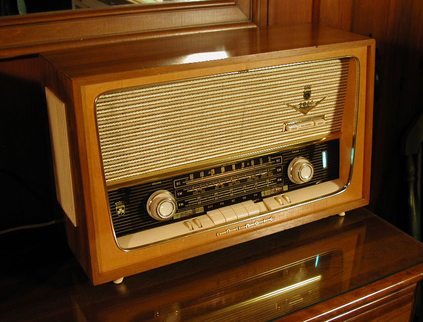
Photo 11. Finally – Work Completed!
October 9, 2007: The Grundig "2066 PX" restored and sounding great again. Notice the "magic eye" tuning tube (driven by the AVC circuit) is fully closed on a strong signal.
26-aug-2007:
Possible loudspeaker problem: With the radio producing the normal amount of power again, a new potential problem surfaced. The loudspeaker could not respond well to low bass tones. The tones sort of "bottomed out" the speaker. I was listening to classical organ music and the low tones were un-readable and distorted. Paper loudspeaker cones can be repaired, and I believe this speaker has a permanent magnet. If all else fails, it may be a standard (6"x9") size. Need to visit "The Speaker Place" in Henrietta, NY and see what they have in the way of advice.
The power transformer may also have overheated enough to melt the insulation and short the windings. The transformer was getting hot before the open resistors and shorted capacitors were replaced. So hot in fact that there were tiny whisps of smoke rising from it at one point. The shorted bypass capacitors were putting a lot of strain on the B+ line and causing it to over-heat. I think finding a "new" transformer will be impossible. Maybe they can be re-wired. This radio continues to provide good learning opportunities!
Note that this Grundig 2066PX radio has two separate bass, and two separate treble controls, similar to a graphic equalizer. There are also three tone control push-button switches on the front of the radio which are labeled "VOICE", "MULTISONIC", and "MUSIC." I used the "multisonic" setting, and was able to eliminate most of the low level distortion by adjusting both of the bass control thumbwheels to their lowest position.
Search online for "pre-emphasis and de-emphasis." For example, www.wikipedia.org says, "Random noise has a 'triangular' spectral distribution in an FM system, with the effect that noise occurs predominantly at the highest frequencies within the baseband. This can be offset, to a limited extent, by boosting the high frequencies before transmission and reducing them by a corresponding amount in the receiver. Reducing the high frequencies in the receiver also reduces the high-frequency noise. These processes of boosting and then reducing certain frequencies are known as pre-emphasis and de-emphasis, respectively.
The amount of pre-emphasis and de-emphasis used is defined by the time constant of a simple RC filter circuit. In most of the world a 50 µs time constant is used. In North America, 75 µs is used. This applies to both mono and stereo transmissions and to base-band audio (not the sub-carriers). The amount of pre-emphasis that can be applied is limited by the fact that many forms of contemporary music contain more high-frequency energy than the musical styles which prevailed at the birth of FM broadcasting."
The discussion on pre-emphasis and de-emphasis seems to indicate that only high frequencies are affected by making changes to the time constant. So, the short term solution might be to simply adjust the two bass thumbwheels and the "tonal contour" push-button switches ("VOICE", "MULTISONIC", and "MUSIC") so as to eliminate the distortion. I will also check the speaker for any cracks or tears.
25-aug-2020:
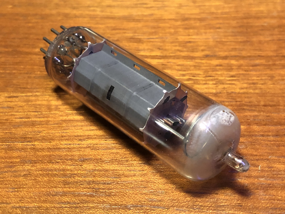
It had been a long time since this page was updated. We were enjoying the radio regularly for 13 years (since the last entry) without any problems, but when it was switched on today, there was no audio – only silence. The detection was still happening because the magic eye tube was still closing up where the stations were on the dial. Took it off the shelf (quite dusty underneath) and down into the basement workshop, and discovered the EL84 (6BQ5) audio amplifier tube had apparently leaked. There appeared to be a fine crack at the tip, and the inside of the glass was "smoke gray" (see photo). With a spare (used) EL84 pressed into service, the set sounded good once again. Let's see how long the used, spare tube lasts. Also ordered a new back-up (spare) EL84 from Antique Electronic Supply (see Radio Links page for URL). The brand was JJ Electronic ($11.05 + $3.95 USPS = $15.00), and it arrived intact on September 1. Note: JJ Electronic began producing vacuum tubes in 1994 in the reorganized Tesla factory in the Slovak Republic.
Update / 25-oct-2020:
Discovered the "Tube Depot" (see Radio Links page for URL) sold the JJ Electronic EL84 for $9.98, which was $1.07 less than Antique Electronic Supply.
Replaced EL84 (6BQ5) Audio Amplifier Tube
Photo 12. Front view
Photo 13. Rear panel
Photo 14. Rear panel detail (tube layout)
Photo 15. bad EL84 (6BQ5) tube with crack at tip
References / Notes
- Adrian's: Troubleshooting The I-F Amplifier Stage page
- Magic Eye tubes: hhscott.com/cc/magic_eyes.htm
- EM84 (6FG6): www.r-type.org/exhib/aaa0079.htm
- Antique Electronic Supply (Arizona). See Radio Links page for URL
- Radio Daze (Rochester, New York). See Radio Links page for URL
- Just Radios (Toronto, Ontario, Canada). See Radio Links page for URL
Acknowledgements
This radio could not have been restored without the help of many people and resources. Contributions were greatly appreciated! From schematics, tube testers, volume controls, miscellaneous parts, oscilloscopes, time, effort, advice, and encouragement – these individuals made it easier to persevere: Ross Hochstrasser ("The Bavarian Radio Works" / Massachusetts), members of the online "Radio Museum" – based in Lucerne, Switzerland (Ernst Erb, Hans M. Knoll, Robert Sarbell [d. March 22, 2022 @ age 82]), Paul Pinyot (KB3LZP/SK), Daniele (Italy), members of the Antique Wireless Association (AWA) – based in Bloomfield, New York (Lynn Bisha [W2BSN], Jack Roubie [deceased], Ed Gable [K2MP]), Bill Burlingame (W2LVP), Tim Brown (WB2PAY), Dr. Stefan Weigelt (Germany), Steve Fischer (Chicago, Illinois), and finally, the "anonymous donor" of the Type EL84 (6BQ5) tube.

c o n t a c t / r a d i o w o r l d
1958-1959 Grundig "2066 PX" AM/FM/SW Radio Restoration
Established: October 22, 2006
Last Update: January 01, 2024
© Black Sparrow Photography / Jeffrey P. Miller (N2AWA)